

Why 0x29 Confuses Engineers: Packet Headers in MIPI DSI Explained
A Complete Guide to Switching Between DCS and Generic Command Sets for the FL7703N Driver IC
On this page
Key takeaways
- In MIPI DSI, 0x29 has two meanings: the Generic Long Write Data ID in a packet header, and the DCS Display ON command in a payload.
- A packet header is 4 bytes: Data ID, two bytes holding the word count (long packets) or the data (short packets), and an ECC byte. Long packets add a payload and a 2-byte CRC footer.
- DCS uses standardized command codes; Generic passes vendor register addresses and values straight to the driver IC.
- IC vendors generally recommend Generic, or Generic plus essential DCS, for initialization, because most initialization code targets vendor registers.
- Switching from DCS to Generic changes only the header Data IDs and the driver API calls; the payload stays the same.
1. Background & The Root of the Communication Misunderstanding
Background: When using a display driver IC (such as the FL7703N), a customer needed to send a sequence of initial code from the host processor to wake up the screen and configure its register settings. Currently, their code uses the DCS format (with Data IDs / DIDs in the packet header set to 0x05, 0x15, and 0x39). Unsure if this choice was optimal, the customer asked us: “Should we switch to the Generic format (e.g., using a DID of 0x29) to send these initialization commands instead?”
The Factory’s Response: The factory engineer completely missed the context and answered with a single line: “0x29 is usually the Display On command, which needs to be enabled.”
The Core Misunderstanding: In the MIPI DSI protocol, the hexadecimal value 0x29 carries a dual identity. The exact same number means two totally different things depending on which command set context you are in. Think of it like a Set Menu A at KFC (which might be fried chicken) versus a Set Menu A at McDonald’s (which might be a burger):
- What the customer asked about (0x29): Refers to the transport-layer Generic Long Write format in the MIPI protocol (Data ID / DID = 0x29 in the packet header).
- What the factory mistook it for (0x29): Refers to the application-layer Display ON command content within the DCS command set (Payload = 0x29).
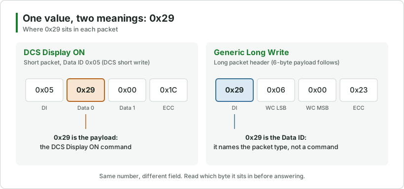
Communication Breakdown Summary: The factory engineer saw 0x29 and instinctively assumed the customer was asking whether to send the ‘Display ON’ turn-on command, failing to read the context carefully. This caused both sides to talk in completely different dimensions—a classic technical ‘talking past each other’.
2. What is a “Packet Header”?
In MIPI DSI communication, the host processor cannot just throw a string of raw data at the screen. Data must be formatted and “packaged” according to protocol standards. A standard MIPI DSI data packet consists of three main parts:
- Packet Header (PH): Located at the very front, occupying a fixed 4 bytes. It acts like a shipping label, telling the receiving IC “what type of data this is (DID)”, “how long the data behind it is (WC)”, and “what the header error check code is (ECC)”.
- Payload (Data): The middle section containing the actual parameters and command content to be written into the registers (the contents inside the shipping box). Short packets do not have a payload; only long packets do.
- Packet Footer (PF): Located at the very end, occupying 2 bytes in long packets for CRC data validation.
Example 1: Basic Data Structure Under DCS Commands
Suppose the host processor needs to send a long-packet configuration command to the FL7703N screen (e.g., containing 6 bytes of configuration parameters):
- Transport Type (DID): DCS Long Write (0x39)
- Word Count / Length (WC): 6 bytes (hexadecimal 0x0006)
- Data Payload: 0xB0, 0x01, 0x02, 0x00, 0x14, 0x00
When this packet is transmitted, these 4 header bytes come first:
| Byte Position | Field Name | Filling Example (Hex) | Function & Detailed Explanation |
|---|---|---|---|
| Byte 1 | DI (Data ID) | 0x39 (DCS Long Write) | [Tells IC Format] Identifies this as a DCS Long Write packet. (Contains Data Type = 0x39 and Virtual Channel = 0 for LCM device 0). |
| Byte 2 | WC LSB (Length Low Byte) | 0x06 (Long Packet) | [Tells IC Length] Low byte of the data length (6 bytes). |
| Byte 3 | WC MSB (Length High Byte) | 0x00 (Long Packet) | [Tells IC Length] High byte of the data length. Combined with Byte 2, it represents 0x0006 (6 bytes). |
| Byte 4 | ECC (Error Correction Code) | 0x30 (Calculated Value) | [Safety Check] Checksum calculated by the host from the first 3 bytes and checked by the receiving IC to detect or correct header bit errors. |
Actual Bus Data Stream (DCS Mode): Concatenating the 4-byte header, 6-byte Payload, and 2-byte CRC footer gives the complete 12-byte data packet transmitted across the physical bus:
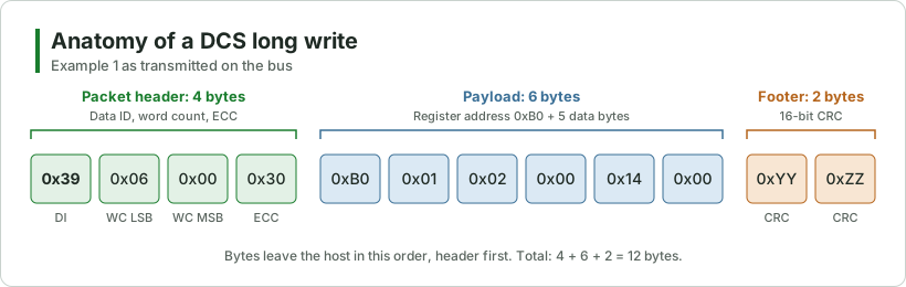
[0x39, 0x06, 0x00, 0x30]  [0xB0, 0x01, 0x02, 0x00, 0x14, 0x00]  [0xYY, 0xZZ]
└───── 4-Byte Header ────┘  └────────── 6-Byte Payload ────────┘  └─ 2-Byte Footer ─┘
Data Verification Process: When the receiving FL7703N IC gets the data, it reads the first 4 bytes first. Seeing that Byte 1 is 0x39 (a long packet) and the word count is 6, the IC knows that 6 bytes of data follow immediately and automatically writes them into the corresponding extension registers.
Example 2: Original DCS C Code Initialization Structure & Stream Breakdown
The original C code struct definition is as follows:
struct dsi_cmd dcs_init_cmds[] = {
    // 1. DID = 0x05: DCS Short Write (0 param) -> Exit Sleep (0x11)
    { .data_type = 0x05, .len = 1, .data = { 0x11 } },
    // 2. DID = 0x15: DCS Short Write (1 param) -> Set Tear On (0x35, 0x00)
    { .data_type = 0x15, .len = 2, .data = { 0x35, 0x00 } },
    // 3. DID = 0x39: DCS Long Write (Multi-param) -> FL7703N Register Configuration
    { .data_type = 0x39, .len = 6, .data = { 0xB0, 0x01, 0x02, 0x00, 0x14, 0x00 } }
};
Low-Level Data Stream Breakdown:
Line 1 (.data_type = 0x05): DCS 0-Parameter Short Write
Transmission behavior: Short packets are fixed at 4 bytes (containing only the header) with no payload behind them.
Actual transmitted byte stream (4 bytes): 0x05, 0x11, 0x00, 0xXX
- 0x05: Header Byte 1 (DI, containing Data Type = 0x05 and VC = 0)
- 0x11: Header Byte 2 (Command content: Sleep Out / Exit Sleep)
- 0x00: Header Byte 3 (No second parameter; 0x00 padding)
- 0xXX: Header Byte 4 (Hardware-calculated ECC checksum)
Line 2 (.data_type = 0x15): DCS 1-Parameter Short Write
Transmission behavior: Short packets are fixed at 4 bytes, with the data carried in header bytes 2 and 3.
Actual transmitted byte stream (4 bytes): 0x15, 0x35, 0x00, 0xXX
- 0x15: Header Byte 1 (DI, containing Data Type = 0x15 and VC = 0)
- 0x35: Header Byte 2 (Command: Set Tear On)
- 0x00: Header Byte 3 (Parameter: 0x00)
- 0xXX: Header Byte 4 (ECC checksum)
Line 3 (.data_type = 0x39): DCS Multi-Parameter Long Write
Transmission behavior: Long packets contain a 4-byte header + 6-byte Payload + 2-byte CRC footer, totaling 12 bytes.
Actual transmitted byte stream (12 bytes): 0x39, 0x06, 0x00, 0xXX | 0xB0, 0x01, 0x02, 0x00, 0x14, 0x00 | 0xYY, 0xZZ
- [0x39, 0x06, 0x00, 0xXX]: Header section. 0x39 is the DID, 0x06, 0x00 indicates 6 bytes of data follow (WC), and 0xXX is the header ECC.
- [0xB0, 0x01, 0x02, 0x00, 0x14, 0x00]: The actual register address and configuration data.
- [0xYY, 0xZZ]: 16-bit CRC checksum for the payload.
3. What are DCS (Display Command Set) & Generic Command Sets?
In MIPI DSI communication, driver ICs (such as FL7703N) typically support two major command sets: DCS (Display Command Set) and Generic. The core differences lie in their degree of standardization and intended application scenarios.
3.1 DCS (Display Command Set)
1. Concept & Positioning: DCS is a highly standardized instruction set defined by the MIPI Alliance specifically for display screens. It specifies a series of 8-bit command codes with fixed meanings, such as 0x11 (Sleep Out / Exit Sleep), 0x29 (Display ON), and 0x35 (Tear On / TE On).
2. Header Types & Data IDs (DID):
- 0x05 (DCS Short Write, 0 param): Transmits DCS commands without parameters (e.g., 0x11 Sleep Out).
- 0x15 (DCS Short Write, 1 param): Transmits DCS commands with 1 parameter (e.g., 0x35, 0x00).
- 0x39 (DCS Long Write): Transmits DCS long data packets containing multiple parameters.
3. Characteristics & Applications:
- High Interoperability: As long as a driver IC adheres to the MIPI DCS standard, basic command meanings remain uniform across manufacturers.
- Purpose-Built: Designed specifically for display control logic, making it ideal for standardized panel operations.
3.2 Generic Command Set
1. Concept & Positioning: Generic is a flexible, custom transmission command set provided by the MIPI DSI protocol. It does not strictly define the specific meaning of internal payload data, instead passing data straight through to the driver IC’s underlying registers. Vendors are free to define proprietary register addresses and configuration parameters.
2. Header Types & Data IDs (DID):
- 0x03 (Generic Short Write, 0 param): Generic short write without parameters (no data bytes).
- 0x13 (Generic Short Write, 1 param): Generic short write with 1 data byte.
- 0x23 (Generic Short Write, 2 params): Generic short write with 2 data bytes (for example, 1 register address + 1 value).
- 0x29 (Generic Long Write): Generic long write with multiple parameters.
Note: Generic counts every data byte as a parameter, while DCS counts the command byte separately. A DCS “0 param” short write (0x05) therefore carries 1 byte, and a DCS “1 param” short write (0x15) carries 2 bytes.
3. Characteristics & Applications:
- Extreme Flexibility: Specifically used for driver IC vendor proprietary extension registers (Vendor Read/Write), such as tweaking panel display quality, Gamma calibration curves, and power timing configurations.
- Agnostic to Standard Command Tables: The host processor simply packages register addresses and values to send over; internal parsing is handled entirely by the driver IC.
4. Switching Between MIPI DSI DCS & Generic Command Sets
This brings us to the customer’s question: Since they currently use the DCS command set, do they need to switch to Generic during initialization, or which command set does the IC vendor recommend for initialization?
The vast majority of LCD/OLED driver ICs (including FL7703N) support both command sets. However, IC vendors generally prefer and recommend using the Generic command set for initialization, or adopting a “Generic-dominated + essential DCS” combination.
Why Do IC Vendors Prefer Generic?
1. Compatibility with Proprietary Registers (Vendor Commands): Over 90% of screen initialization code (such as power sequencing, Gamma tuning, internal clock division) consists of vendor-specific extension registers. Generic format acts as standard “data pass-through”, delivering addresses and values straight to registers without protocol-level constraints.
2. Better Long-Packet Compatibility: In many host platform MIPI drivers (e.g., Linux / Android kernel), the default packaging function used for vendor multi-byte initialization long packets is Generic Long Write (0x29).
3. Native Support for 2-Parameter Short Writes (0x23): When configuring “1 register address + 1 value”, Generic can send it directly as a 0x23 short packet. In DCS, the same 2 bytes go out as a 0x15 short write (command + 1 parameter); anything longer than 2 bytes needs a long packet in either set (0x39 or 0x29).
Switching from DCS to Generic requires zero changes to the configuration data payload; it only involves updating the packet header Data ID mapping and driver API calls.
DCS vs. Generic DID Mapping Table
| Current DCS DID | Generic Equivalent DID | Change Details |
|---|---|---|
| 0x05 (0 Parameter: command byte only, 1 byte) | 0x13 (Generic Short Write, 1 byte) | Keep the same 1 byte; replace header DID only |
| 0x15 (1 Parameter: command + 1 parameter, 2 bytes) | 0x23 (Generic Short Write, 2 bytes) | Keep the same 2 bytes; replace header DID only |
| (N/A in DCS) | 0x03 (Generic Short Write, no data) | A DCS write always carries a command byte |
| 0x39 (Multi-Parameter Long) | 0x29 (Generic Long Write) | Keep multi-parameter long packet; replace header DID only |
Example 3: Code Comparison for Replacing DCS with Generic in C
// ==================== 1. Legacy DCS Initialization Sequence ====================
struct dsi_cmd dcs_init_cmds[] = {
    { .data_type = 0x05, .len = 1, .data = { 0x11 } },               // Exit Sleep
    { .data_type = 0x15, .len = 2, .data = { 0x35, 0x00 } },         // TE On
    { .data_type = 0x39, .len = 6, .data = { 0xB0, 0x01, 0x02, 0x00, 0x14, 0x00 } }
};

// ==================== 2. Recommended Generic Initialization Sequence ====================
struct dsi_cmd generic_init_cmds[] = {
    { .data_type = 0x13, .len = 1, .data = { 0x11 } },               // 0x05 -> 0x13
    { .data_type = 0x23, .len = 2, .data = { 0x35, 0x00 } },         // 0x15 -> 0x23
    { .data_type = 0x29, .len = 6, .data = { 0xB0, 0x01, 0x02, 0x00, 0x14, 0x00 } }  // 0x39 -> 0x29
};
Specific Transition Steps:
Step 1: Modify Packet Header Data IDs (.data_type)
According to the mapping table, replace .data_type entries directly in your initialization array:
- 0-Param Short Write (1 byte): 0x05 ➡️ Change to 0x13
- 1-Param Short Write (2 bytes): 0x15 ➡️ Change to 0x23
- Multi-Param Long Write: 0x39 ➡️ Change to 0x29
Step 2: Adjust Driver-Layer Sending APIs (If Platform-Differentiated)
Taking common Linux / RTOS kernel drivers as an example:
- DCS Mode APIs: mipi_dsi_dcs_write_buffer() or mipi_dsi_dcs_write()
- Generic Mode APIs: mipi_dsi_generic_write() (or mipi_dsi_generic_write_seq_multi() in current kernels)
Note: When switching APIs, simply pass in the original register data array. The payload data itself requires no header prepending or modification.
5. Recommended Customer Response Template & Final Conclusion
Suggested Customer Reply Template:
“For the FL7703N chip, we recommend prioritizing the Generic command set for initialization. Since most commands in the initialization sequence target vendor-proprietary extension registers, Generic’s 0x29 (long write) and 0x13/0x23 (short write) offer superior compatibility.
Transitioning is simple: keep your configuration parameter arrays (e.g., 0xB0, 0x01…) completely unchanged, replace the header .data_type values from DCS (0x05/0x15/0x39) to their Generic equivalents (0x13/0x23/0x29), and call your platform’s mipi_dsi_generic_write API.”
Final Conclusion: In practical engineering, changing the packet header Data ID (e.g., from 0x39 to 0x29) has zero impact on the validity or content of the Payload data. Payload values are filled strictly according to the chip’s datasheet.
At this point, everything becomes crystal clear: our 0x29 (Generic Long Write packet header) and the factory’s 0x29 (Display ON command payload) are two completely different things!
Frequently asked questions
What does 0x29 mean in MIPI DSI?
What is in a MIPI DSI packet header?
What is the difference between DCS and Generic commands?
Which Data IDs replace the DCS ones when switching to Generic?
Does switching from DCS to Generic change the payload?
New engineering articles by email.
Keep reading
Display Interfaces Explained
Embedded DisplaysDisplay Controller and Driver ICs
ReferenceDisplay Interface Quick Reference
Driver ICs & InterfacesSPI Displays Are Not Video Streams: Understanding Command Mode LCDs
Driver ICs & InterfacesLCD Power-on Process
Driver ICs & InterfacesIntroduction to Embedded Touch Display Driver Chip (TDDI)
Bringing up a MIPI DSI panel?
Talk to an engineer about initialization code and driver IC configuration for your display.