

Capacitive Touch Screens in Deep Water: Comprehensive Analysis of Water & Saline Resistance Design
How water and saline films fool self-capacitance sensing, why active shielding breaks down in saltwater, and where mutual capacitance fits.
On this page
Technical Engineering Blog | Electric Field Topologies & Environmental Touch Performance Analysis
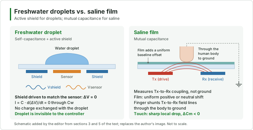
Abstract: In modern human-machine interface (HMI) design for automotive, marine, outdoor, and industrial electronics, moisture resistance has evolved from a nice-to-have feature into a critical compliance requirement. While preventing false touches from freshwater droplets is standard practice today, enabling reliable touch interaction under conductive saline or marine water films presents a far greater physical hurdle.
This technical post provides a comprehensive engineering breakdown of capacitive touch topologies, water-induced false trigger mechanics, active shielding principles, and why mutual capacitance serves as the ultimate architecture for saltwater resistance.
Key takeaways
- Self-capacitance cannot tell a finger from other grounded conductive media, so water on the panel can register as a touch.
- An active shield driven to match the sensor (ΔV = 0) stops current through freshwater droplets, so the controller does not see them.
- Saline forms a continuous low-impedance film that capacitively couples sensor, shield and ground, overloads the shield driver and saturates the sensor.
- Mutual capacitance measures Tx-to-Rx coupling: a saline film adds only a uniform baseline offset, while a finger causes a sharp local drop (ΔCm < 0).
1. The Foundation: Physical Topologies of Self-Capacitance vs. Mutual-Capacitance
Before analyzing environmental moisture interference, it is essential to review the fundamental physical architectures of capacitive touch sensing:
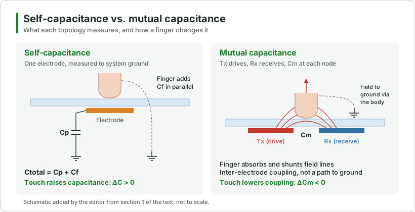
- Self-Capacitance Topology: Each sensor electrode functions independently as a single conductive plate, measuring the total parasitic capacitance relative to system ground (GND): Ctotal = Cp + Cf. When a finger touches the surface, the human body introduces an additional parallel capacitance Cf, causing total measured capacitance to rise sharply (ΔC > 0). While self-capacitance supports thick cover lens materials, glove operation, and long-range proximity sensing, it inherently lacks the ability to differentiate a human finger from other grounded conductive media.
- Mutual-Capacitance Topology: Constructed via orthogonal drive (Tx) and receive (Rx) electrode matrices, measuring the mutual coupling capacitance Cm across intersection nodes. When a finger approaches a node, it absorbs and shunts electric field lines to ground, causing a sharp drop in mutual capacitance (ΔCm < 0). Because mutual capacitance measures inter-electrode coupling rather than a direct return path to ground, it inherently supports true multi-touch tracking and remains unaffected by baseline parasitic capacitance to ground.
2. Water Droplet Interference: False Trigger Mechanics in Self-Capacitance
When liquid water contacts a self-capacitive touch panel, it induces false touches through two primary physical phenomena:
- High Dielectric Permittivity (εr ≈ 80): Water possesses a relative dielectric permittivity of approximately 80 at room temperature, compared to 1.0 for ambient air. Liquid droplets sitting above an electrode act as dielectric lenses, concentrating electric field lines and increasing local parasitic capacitance.
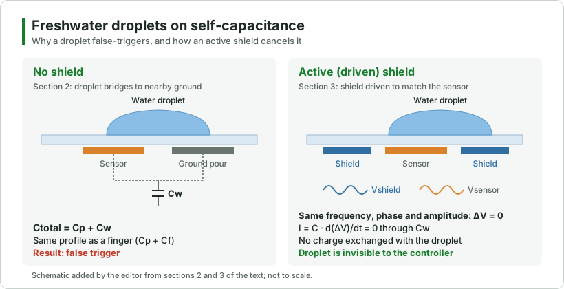
- Conductive Bridging (Cw Introduction): When raindrops or condensation bridge a sensor electrode to neighboring ground copper pours or adjacent inactive traces, the water acts as a conductive bridge, introducing a parallel water capacitance Cw.
- Algorithmic Ambiguity: The sensing controller measures a total capacitance increase (Ctotal = Cp + Cw) that mirrors the signal profile of a true finger touch (Cp + Cf). Consequently, standard baseline threshold algorithms cannot distinguish between liquid droplets and finger touch events, resulting in unwanted false triggers.
3. Active Shielding: Mitigating Freshwater Interference
To neutralize the impact of isolated freshwater droplets, touch system architectures employ Active Shielding (Driven Shield) technology:
- Equipotential Driving Principle: A dedicated shield electrode surrounding the sensor channels is driven with an excitation waveform that perfectly matches the sensor electrode in frequency, phase, and amplitude (Vshield = Vsensor), maintaining an instantaneous voltage differential of ΔV = 0.
- Zero-Current Displacement: According to the fundamental charge displacement equation I = C · d(ΔV)/dt, forcing ΔV = 0 eliminates current flow through the water droplet capacitance Cw. As a result, no charge is exchanged between the sensor and the water droplet, rendering liquid droplets electrically ‘invisible’ to the controller during scanning.
4. Saline Failure: Why Active Shielding Fails in Saltwater
While active shielding resolves freshwater droplet issues, it experiences total physical breakdown when exposed to saline solutions, seawater, or heavy perspiration:
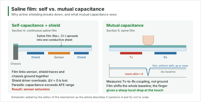
- Continuous Low-Impedance Conductive Film: Unlike purified water, saline solution contains dissolved sodium (Na+) and chloride (Cl-) ions, converting the liquid from a weakly conductive liquid into a highly conductive, low-impedance liquid layer. Saline rapidly spreads across the cover glass, forming a continuous conductive sheet.
- Active Shield Driver Overload: The continuous saline film capacitively couples sensor electrodes, active shield traces, and distant system chassis ground points together. This massive conductive path overloads the active shield driver circuitry, collapsing the equipotential condition (ΔV = 0 premise destroyed).
- Parasitic Capacitance Saturation: With the sensor effectively capacitively coupled to system earth ground via the saline film, parasitic capacitance surges beyond the analog front-end (AFE) dynamic sampling range, locking the sensor into permanent saturation.
5. Mutual-Capacitance Resolution: The Ultimate Solution for Saline Touch
To overcome the capacitive coupling caused by continuous saline films, mutual-capacitance touch sensing offers an optimal architecture:
- Resistance to Saline Coupling: Because mutual capacitance measures node coupling strictly between Tx and Rx electrodes rather than referencing system ground, a conductive liquid film covering the panel acts as a uniform conductive plane. This introduces a slight, global baseline offset rather than sharp localized signal spikes.
- Clear Signal Absorption Signature: When a grounded human finger touches the saline-covered panel, it shunts Tx-to-Rx electric field lines directly through the human body to ground. This creates a sharp, localized drop in mutual capacitance (ΔCm < 0) at the exact touch coordinate.
- Algorithmic Separation: Because the finger touch produces a distinct negative capacitance delta (ΔCm < 0) while the saline film only causes a uniform positive or neutral baseline shift, advanced digital signal processing (DSP) algorithms can easily isolate genuine user inputs even under heavy saltwater surface coverage, provided the system is engineered with proper grounding and controller tuning.
6. Touch Architecture & Physical Mechanism Summary
| Application Scenario | Recommended Topology | Core Physical Mechanism & Strategy |
|---|---|---|
| Normal Dry Environment | Self-Capacitance | Detects overall capacitance-to-ground increase (ΔC > 0) caused by conductive finger coupling. |
| Freshwater / Raindrops | Self-Capacitance + Active Shield | Applies equipotential drive (ΔV = 0) to shield electrodes, eliminating charging current through water droplets. |
| Saltwater / Saline Film | Mutual-Capacitance | Measures Tx-to-Rx field reduction (ΔCm < 0); resists false triggers from conductive saline films when paired with proper grounding and tuning. |
Frequently asked questions
Why does water cause false touches on a self-capacitance panel?
How does active shielding reject freshwater droplets?
Why does active shielding fail in saltwater?
Why does mutual capacitance work under a saline film?
Which touch topology fits which environment?
New engineering articles by email.
Keep reading
Resistive vs Capacitive Touch
Design and IntegrationCover Glass and Surface Treatments
Design and IntegrationOptical Bonding Explained
Touch PanelsSITO vs DITO Touch Panel Architecture
Touch PanelsFPC Capacitive Key: A Simple Way to Think About Touch
Display Selection & ApplicationsOutdoor Display Design Checklist
Specifying touch for a wet or marine environment?
Talk to an engineer about touch topology, controller tuning and cover glass for your application.