

How an LCD Is Made
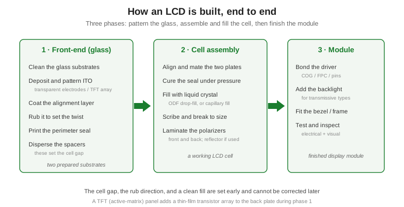
An LCD is not printed in one pass; it is built up in three phases. First the two glass plates are cleaned, coated with transparent electrodes, and given an alignment layer that is rubbed to set the direction the liquid crystal will twist. Then the plates are sealed a few microns apart, filled with liquid crystal, cut to size, and fitted with polarizers to make a working cell. Finally the cell gets a driver, a backlight if it needs one, and a frame to become a finished module. The order matters, because the cell gap and the rub direction are locked in early and cannot be fixed later. For what this cell actually does once built, see what an LCD is and how it works.
Part of the Display Fundamentals knowledge hub.
Phase 1: patterning the glass
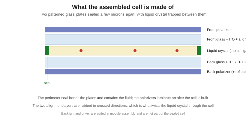
Both substrates start as ultra-clean glass. A thin, transparent conductor called indium tin oxide (ITO) is sputtered onto each and then photolithographically etched into the electrode pattern: simple segments and a common backplane for a static display, or a fine grid of rows and columns for a multiplexed one. On an active-matrix panel this is where the thin-film transistor array is built onto the back plate, one transistor per sub-pixel. Each plate then receives a polyimide alignment layer, which is buffed in one direction with a cloth roller. That microscopic rubbing is what tells the liquid crystal which way to lie against the glass, and rubbing the two plates in crossed directions is what makes the fluid twist through the cell. The electrode pattern decides how the display is addressed, which is the subject of how LCDs are driven.
Phase 2: assembling and filling the cell
A bead of epoxy seal is printed around the perimeter of one plate, and tiny spacers, either sprayed-on beads or photo-patterned posts, are placed to hold the two plates a precise distance apart. That distance is the cell gap, typically three to six microns, and it has to be uniform across the whole display or the contrast and color will vary. The plates are aligned to each other, mated, and the seal is cured under pressure. The empty cell is then filled with liquid crystal.
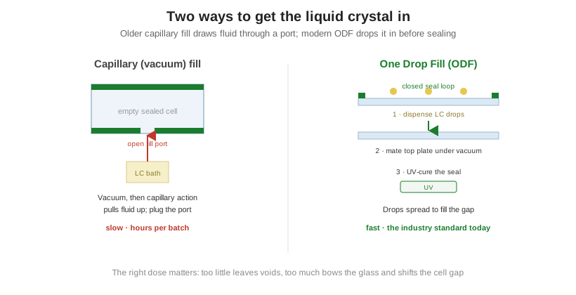
There are two ways to fill it. The older capillary method seals the cell with a small open port, evacuates the air, and lets vacuum and capillary action draw fluid in through the port, which is then plugged; it works but is slow. Nearly all modern production uses One Drop Fill (ODF): metered drops of liquid crystal are dispensed inside a closed seal loop on one plate, the second plate is lowered onto it under vacuum, and the seal is UV-cured. The drops spread to fill the gap exactly. Dose control is critical, because too little fluid leaves voids and too much bows the glass and shifts the cell gap.
Whichever fill is used, the filled sheet is scribed and broken into individual cells, and then the polarizers are laminated onto the outer faces, one on the front and one on the back. A reflective or transflective display also gets a reflector behind the back polarizer at this stage. At the end of phase 2 you have a complete, working LCD cell.
Phase 3: building the module
A bare cell still needs electronics and, usually, light. The driver IC is bonded on, most often chip-on-glass (COG) directly onto the panel, or through a flex circuit (FPC) or a row of pins to a host board. Transmissive displays get a backlight assembly, an LED light guide stacked behind the cell. A metal or plastic bezel holds everything in register, and the finished module is tested both electrically and visually before it ships. This last phase turns the cell into the display module a product actually designs around.
The steps at a glance
| Phase | Key steps | What it sets |
|---|---|---|
| 1. Front-end (glass) | Clean, deposit and pattern ITO (and TFT array), coat and rub the alignment layer, print seal, place spacers | Electrode pattern, twist direction, cell gap |
| 2. Cell assembly | Align and mate the plates, cure the seal, fill with liquid crystal (ODF or capillary), scribe and break, laminate polarizers | A working LCD cell |
| 3. Module | Bond the driver (COG/FPC/pins), add the backlight, fit the bezel, test and inspect | The finished display module |
Orient Display runs this full process in-house, from ITO patterning and cell assembly through backlight and module build, for custom character, graphic, and TFT displays. Choosing the cell gap, fluid, and drive scheme together is what makes a display meet its contrast, temperature, and viewing spec. The full range is in the LCD product line.