
Blog
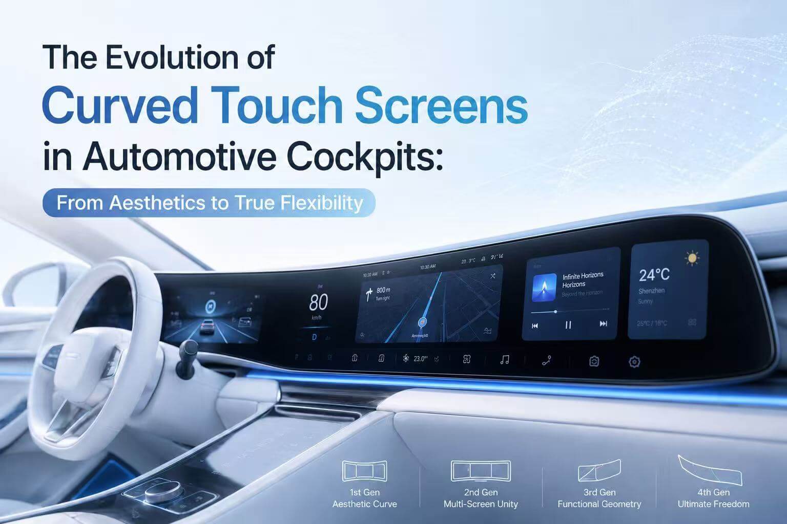
The Evolution of Curved Touch Screens in Automotive Cockpits: From Aesthetics to True Flexibility
The modern automotive cockpit is undergoing a massive design shift. Gone are the days of rigid, flat, rectangular screens slapped onto the center console. Today, tiers and OEMs are treating the dashboard as a continuous, flowing canvas.
Designing a Curved Touch Screen introduces unique optical, mechanical, and manufacturing complexities that don’t exist with flat glass. Understanding how these screens are built—and where the technology is heading—is crucial for display engineers, product managers, and industrial designers alike.
Let’s break down the four distinct generations of curved touch screen technology, evaluating the mechanical engineering, bonding constraints, and material science behind each.

The 4 Generations of Curved Touch Screen Technology

1st Gen: The “Aesthetic” Curve (IML + Flat Glass Touch)

In the early days of curved automotive interiors, the display technology wasn’t curved. The active display area and button area remained completely flat.
Instead, the curvature was restricted entirely to the border/mid area using In-Mold Labeling (IML) or injection-molded plastic trim. A flat glass touch panel was embedded inside a curved housing. While this achieved a fluid look on the dashboard, it lacked seamless integration; the distinct boundary between the flat screen and the curved plastic frame remained highly visible.
2nd Gen: The Multi-Screen Unity (Cold Bending Lens + Glass Touch)

To achieve a premium, single piece look without a massive price tag, the industry developed Cold Bending. This is currently the dominant technology for large, integrated dual or triple-screen setups (the “pillar-to-pillar” display).
- The Architecture: The underlying LCD display panels and touch sensors are flat, but they are covered by a single, large sheet of protective glass that is curved in the middle or at the borders.
- The Process: Glass is chemically strengthened while perfectly flat. During final assembly, it is mechanically forced into a curved bezel frame at room temperature.
- Engineering Advantage: Because the glass isn’t heated, it retains pristine optical quality, suffers no thermal distortion, and keeps manufacturing costs relatively low. However, it is strictly limited to shallow, gentle 2D cylindrical bends because the glass remains under constant internal mechanical stress.
3rd Gen: Functional Geometry (Hot Bending Lens + Glass/Film Touch)

When a design demands aggressive curves, or a complex 3D shape—cold bending fails, which is Hot Bending.
- The Architecture: The primary display area remains flat (to accommodate rigid LCDs), but the button/control area transitions into a steep curve, forming a waterfall screen or an L-shaped console.
- The Process: Flat glass is placed over a precise graphite mold and heated to its softening point (around 600°C–700°C). Gravity or pressure shapes the glass to the mold. Crucially, chemical strengthening must happen after this thermal process, otherwise, the heat destroys the tempering layer.
- The Challenge: Because the touch area now wraps around a tight radius, traditional rigid Glass-on-Glass (GG) touch sensors can crack. Engineers must transition to Film-based touch sensors (Metal Mesh or AgNW on PET) that can flex to conform to the inner curvature of the hot-bent lens.
4th Gen: Ultimate Freedom (True Flexible Touch & Display)

The cutting edge of cockpit design abandons flat internal components altogether. In the 4th generation, both the display area and the touch sensor are natively curved.
- The Architecture: The screen seamlessly flows along the contours of the dashboard, fitting curved instrument clusters or wrapping around the driver in a semi-enclosed cockpit.
- The Technology: This relies on Flexible OLED substrates paired with CPI (Colorless Polyimide) or ultra-thin flexible touch sensors.
- Performance Metrics: These assemblies utilize sensors engineered to withstand tight bending radius, and endure over 200,000 bending cycles, offering massive design freedom while maintaining high reliability in harsh environments (operating from -40C up to 95C).
Key Engineering Challenges in Curved Display Design
Whether implementing a Gen 2 cold-bent system or a Gen 3 hot-bent module, front-end design requires balancing several physical trade-offs:
-
Bonding Methodology: OCA vs. OCR
Connecting a curved cover lens to the display panel is a major yield-rate variable.
- OCA (Optically Clear Adhesive) Tape: Standard flat OCA films tend to struggle on curved surfaces. The internal rebound stress of the bent glass causes the tape to pull away at the edges, leading to delamination and bubbles over time.
- OCR/LOCA (Optically Clear Resin / Liquid Glue): Liquid bonding is highly preferred for curved geometries. The liquid flows naturally to fill the uneven tolerances and gaps created by the curve. However, it requires highly specialized fixture tooling to prevent overflow and ensure a completely uniform bond-line thickness across the bend.
-
Optical Distortion and Reflection Management
Curved surfaces inherently behave like lenses. As the radius of curvature sharpens, light traveling from the flat display through the curved glass bends, causing visual distortion, ghosting, or color shifts at wide viewing angles.
Furthermore, while flat glass reflects ambient light in one predictable direction, a curved surface captures and concentrates glare from multiple angles. Specifying high-performance Anti-Reflective (AR) and Anti-Glare (AG) coatings is mandatory. However, depositing these coatings uniformly across a steep 3D curved surface without pooling or thinning at the apex is a major manufacturing hurdle.
-
Dimensional Tolerance Stack-up
Thermal bending introduces minor batch-to-batch variations in the exact radius of curvature. If the inner radius of your cover glass doesn’t perfectly match the profile of the display or mounting bracket, it creates uneven pressure points. In production, this can cause localized pooling of liquid glue, leading to visual artifacts on the display (the Mura effect) or, worse, causing the display panel to crack under mechanical stress.
Conclusion
The evolution of the curved touch screen is a journey of removing mechanical constraints from user experience design. While Gen 2 cold bending offers an excellent middle ground for cost-effective, wide screen setups today, the future belongs to Gen 4 flexible architectures.
As material science advances in flexible substrates and high-reliability liquid optical bonding, the dashboard will transition from a place where displays are mounted, to a surface that is entirely a display.

If you have questions or would like to explore your next design, please contact our engineering.
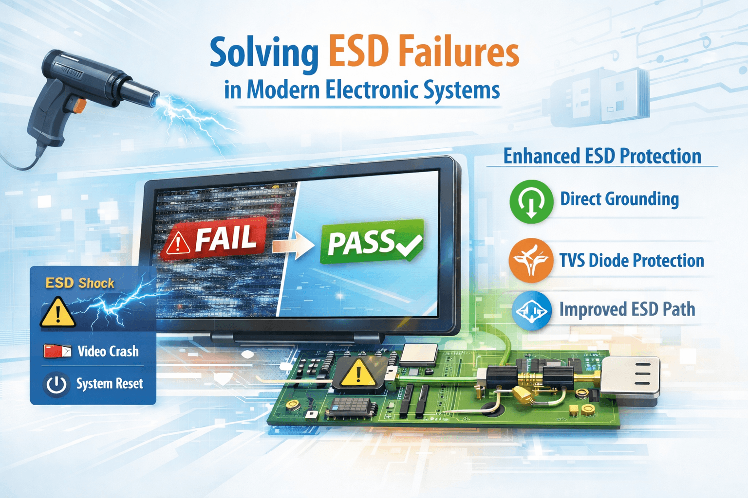
Solving ESD Failures in Modern Electronic Systems
Case Overview – Improving ESD Reliability in large size USB Display System
The exiting display system was upgraded from an older LVDS design to a new USB‑based architecture. During certification testing, the system passed the 8 kV contact discharge test but failed the 15 kV air discharge test. This caused video interruptions and system resets, preventing the product from being approved.
Our engineering team analyzed the issue and identified two main causes:
- The USB ground path had too much resistance during an ESD event.
- The USB power line did not have strong enough protection against voltage spikes.
After making targeted improvements, the system able to successfully pass the 15 kV air discharge test.
What Was Happening?
During testing, an ESD gun applies a high‑voltage static shock to the outside of the device. This simulates real‑world situations such as a user touching the screen after walking on carpet.
This shock caused the USB interface to momentarily fail, which led to:
- Video freezing
- Display blackouts
- Touch panel communication loss
- System resets
This happened because the USB interface is more sensitive to static electricity than the older LVDS design.
Root Cause Debug
-
Grounding Was Too Weak for ESD
The USB ports used ferrite beads between the connector and ground. Ferrite beads are good for filtering noise, but they block fast, high‑energy ESD pulses. This prevented the static charge from safely going to ground.
-
The USB Power Line Needed Better Protection
The USB 5 V line did not have a fast‑acting protection device to absorb sudden voltage spikes caused by ESD.
What We Changed
To fix the issue, we made four improvements:
✔ Direct Grounding
We removed the ferrite beads (L15 and L20) and connected the USB ground directly to the system ground.
This gives static electricity a clean, low‑resistance path to escape.
✔ Added TVS Protection
We added a high‑speed TVS diode (SP1326‑01LTG) to the USB 5 V line.
This device instantly clamps voltage spikes and protects the USB controller.
✔ Improved ESD Path
The new grounding and protection layout ensures that ESD energy is safely diverted away from sensitive components.

Figure 1

Figure 2
How the Improved Design Works
Before Fix
ESD Shock → Ferrite Bead → Blocked → USB Chip Overloaded → Video Failure
After Fix
ESD Shock → Direct Ground → TVS Clamp → USB Chip Protected → System Stable
Results
After applying these improvements:
- The system passed 15 kV air discharge
- No video dropouts or resets occurred
- USB communication remained stable
- The product is now ready for certification, BINGO!!
Conclusion
The ESD failures were caused by grounding impedance and insufficient surge protection in the USB interface. By optimizing the ground path and adding proper TVS protection, we restored the system’s reliability and ensured it meets certification requirements.
If you have any questions, please contact our engineering.
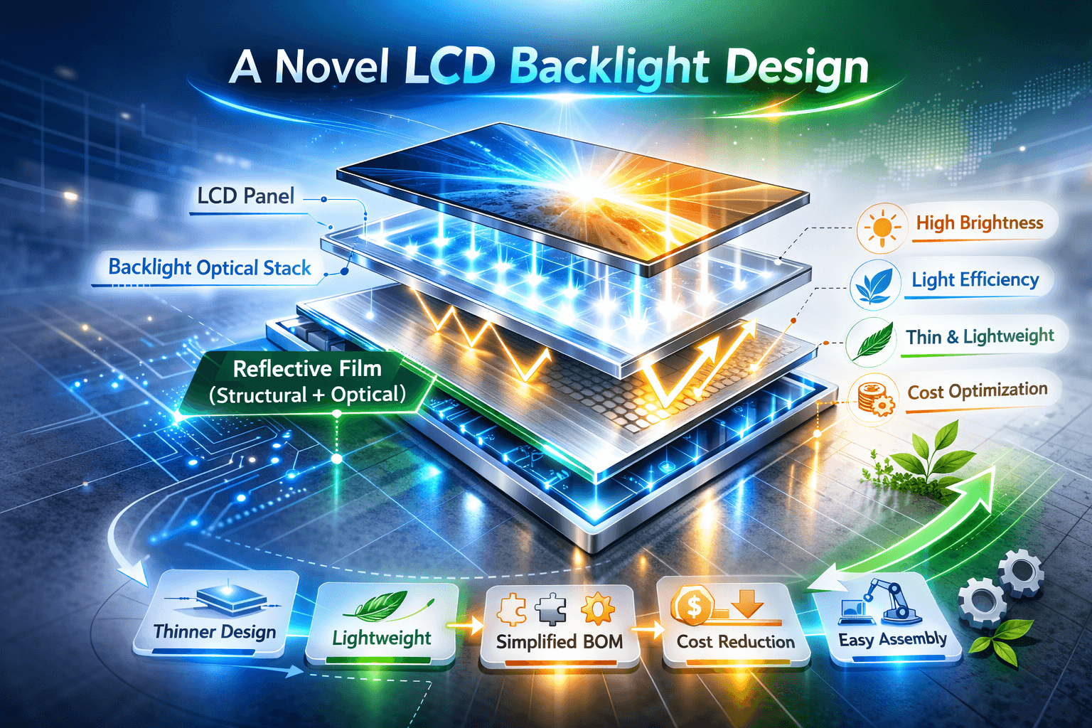
A Novel LCD Backlight Design
A reflective film is an optical component used within a display’s backlight assembly to recycle light and increase brightness/efficiency, whereas a plastic backlight is a type of complete backlighting unit structure, often utilizing an edge-lit design with light guide plates and various films, including a reflective film as its bottom layer.
The Optical Reflective Film for Liquid Crystal Display (LCD) market refers to a specialized segment in the electronics and display technology industries, driven by the growing demand for high-quality visual experiences. Optical reflective films are primarily used in LCD panels to improve their brightness and contrast by reflecting and optimizing light. These films contribute to enhancing the clarity, color accuracy, and overall display performance of devices like televisions, smartphones, tablets, and monitors. The global demand for such technology has surged in recent years, as consumers and businesses alike seek displays with superior image quality and energy efficiency.

Traditional Module Structure
- LCD Glass
- Backlight Optical Stack
- Backlight Reflector Sheet
- Plastic Frame / Plastic Housing
- Metal Back Plate
Functional separation
- Optical function: Backlight reflector
- Structural function: Plastic frame
- Encapsulation function: Frame + back shell
Reflective Film Bottom Design (Intergraded Structure)
- LCD Glass
- Backlight Optical Stack
- Reflective Film (Structural + Optical)
- Integrated Sealing Layer (No Plastic Frame)
Integrated Functionality
- Optical Reflection
- Bottom Packaging
- Structural Support
- Module Fixing
- Thickness Control
In order to achieve below Engineering Objectives
- Module thinning design
- Lightweight structure
- Simplified BOM structure
- Optimized cost structure
- Automation-friendly assembly
- Integrated module design
Overall, compared with a conventional plastic backlight housing, the reflective-film bottom design achieves a thinner profile and lower weight, while the plastic backlight structure provides higher mechanical robustness.

Q&A for Reflective Film Bottom design
Question 1: Are the Reflective film bottom design meets structural strength and aging resistance requirements?
Answer: It meets the requirements. The structural strength must not only be provided by the LCD module itself, but the overall structure of the complete device housing must also protect the LCD module. In terms of aging test, it is no different from products with plastic frame bottom sealing.
Question 2: Is it able to meet the compatibility of thermal expansion and contraction?
Answer: Yes, Orient Display factory able to meet this requirement.
Question 3: Is the Reliability testing (vibration, drop, thermal cycling), will also be performed for reflective film bottom design LCD?
Answer: Yes, Orient factory able to perform the same Reliability test accordingly.
Question 4: Is the reflectivity able meet the backlight luminous efficacy requirements?
Answer: Yes, we can meet this requirement.
Question 5: Is the bottom sealing structure able to meet IP protection design requirements?
Answer: There is no problem with dust protection. However, the waterproof performance of an individual product is slightly worse than that of a product with a sealed bottom frame. If the entire machine is properly protected, the performance is the same.
If you have any questions, please contact our engineering.
Optimizing LCD Cover Glass for Enhanced IR Sensor Performance
When designing applications that rely on infrared technology—be it a sleek smartphone with facial recognition or a responsive optical touch interface—a critical challenge often arises: the cover glass, meant to protect the display, can significantly attenuate the IR signal.
Orient Display FAE team is here to help! This essay offers a clear comparison of glass types and thicknesses to guide you in selecting a solution that maximizes transmittance and ensures end-user reliability.
What is Light Transmittance of LCD Glass Cover?
Light transmittance refers to the percentage of incident light that can pass through the glass cover of a display. It is expressed in percentage (%).
Example: A transmittance of 85% means 85% of the incoming light can pass through the glass.
Factors Affecting LCD Cover Glass Transmittance
| Factor | Description & Impact |
| Glass Type | The material composition is fundamental. Soda-lime glass, Ultra-clear glass (low-iron), and Aluminosilicate glass (e.g., Gorilla Glass) have different inherent transmittance. Low-iron glass typically offers higher transmittance. |
| Thickness | Thicker glass leads to greater light absorption and scattering. Thinner glass generally provides higher transmittance. For example, transmittance may increase from ~81% at 2.9 mm to ~87% at 2.0 mm for Soda-lime glass. |
| Surface Coating | Coatings like Anti-Glare (AG), Anti-Reflection (AR), and Anti-Fingerprint (AF) alter how light interacts with the surface. While AG may reduce it, AR coating is specifically designed to increase transmittance by reducing surface reflection. |
| Polarizer Attachment | Adding a polarizer changes the light’s polarization state and typically reduces overall transmittance significantly. Special “high-brightness” polarizers can recover a small amount (~1.3-1.5%). |
| Boarder Silk Screen Printing | Black ink printing on the borders is opaque and blocks all light. This does not affect the material’s intrinsic transmittance but reduces the effective viewable area for light transmission. |
Why 940 nm Is Important in LCD Applications
While visible-light transmittance affects display brightness and clarity, the transmittance at infrared wavelengths—especially around 940 nm.
940 nm refers to the wavelength of infrared light, the transmittance of cover glass at 940 nm is critical for ensuring accurate sensor performance, Infrared light (IR) at 940 nm is widely used in proximity sensors, facial recognition, optical touch, and remote-control systems because it is safe, energy-efficient, and undetectable to the human eyes.
Many modern electronic devices integrate sensors that rely on infrared light. These components are often located behind the cover glass of displays or touch panels.
| Application | Usage of 940 nm IR |
| Smartphone face recognition | IR illumination and depth sensing |
| Proximity & gesture sensors | IR reflection and detection |
| IR touch and in-display fingerprint | Optical transmission through cover glass |
| Remote controls / IR communication | 940 nm IR LED |
| TOF (Time-of-Flight) sensors | Distance and depth mapping |
For these functions to work properly, the cover glass must allow sufficient infrared light to pass through. In many specifications, a minimum IR transmittance (such as ≥80% at 940 nm) is required.
Glass Material Effect
Different glass types have different absorption characteristics for near-infrared light.
| Glass Type | Transmittance at 940 nm |
| Standard soda-lime glass | ~75–82% |
| Low-iron ultra-clear glass | ~85–90% |
| Gorilla/ Dragontrail or aluminosilicate glass | ~88–92% |
Infrared Transmittance at 940 nm — by Glass Type & Thickness
Standard Soda-Lime Glass
| Thickness | Typical IR Transmittance at 940 nm |
| 3.0 mm | 74% – 78% |
| 2.9 mm | 79% – 81% |
| 2.5 mm | 80% – 82% |
| 2.0 mm | 83% – 87% |
| 1.1 mm | 85% – 87% |
| 0.7 mm | 86% – 88% |
Low-Iron Ultra-Clear Glass
| Thickness (mm) | Typical IR Transmittance at 940 nm (%) |
| 3.0 mm | 84% – 87% |
| 2.9 mm | 85% – 87.5% |
| 2.5 mm | 87% – 89% |
| 2.0 mm | 89% – 91% |
| 1.1 mm | 91% – 93% |
| 0.7 mm | 92% – 94% |
* Low iron reduces absorption and improves clarity, especially helpful for both visible and infrared wavelengths.
Aluminosilicate / Gorilla Glass/ Dragontrail
| Thickness (mm) | Typical IR Transmittance at 940 nm (%) |
| 2.9 mm | 88% – 90% |
| 2.0 mm | 90% – 92% |
| 1.5 mm | 91% – 93% |
| 1.1 mm | 92% – 94% |
| 0.7 mm | 93% – 95% |
Chemically strengthened aluminosilicate glass has the best infrared transmittance, making it ideal for cover glass over sensors, cameras, and biometric modules.
Comparison Summary
| Glass Type | IR Performance | Strength | Cost | Typical Usage |
| Standard Soda-Lime | Low | Low | ★ | Basic cover glass, low-cost devices |
| Low-Iron Ultra-Clear | Medium | Medium | ★★ | Displays, automotive, touch cover |
| Aluminosilicate | High | High (chem-strengthened) | ★★★ | Premium cover glass, sensor window, face/fingerprint ID |
Application Guidance
| Use Case | Recommended Glass |
| Standard display cover | Standard soda-lime or low-iron glass |
| High-brightness display | Low-iron ultra-clear glass |
| Optical/fingerprint touch | Low-iron or aluminosilicate glass |
| Face ID / IR sensing / camera | Aluminosilicate (thin, high IR transmission) |
| Automotive HUD / display | Low-iron or aluminosilicate |
Surface Coating Influence infrared performance differently
| Coating Type | IR Impact |
| AR (Anti-Reflection) | Improves IR transmittance |
| AG (Anti-Glare) | May scatter and reduce IR |
| AF (Anti-Fingerprint) | Minimal effect |
| IR-blocking film | Blocks infrared transmission |
Selecting the optimal cover glass is a strategic decision that extends beyond durability and cost. For devices featuring facial recognition, proximity sensing, or optical touch, the cover glass serves as the critical optical gatekeeper. The data presented confirms that by prioritizing high-transmittance materials—such as low-iron or aluminosilicate glass—and minimizing thickness, engineers can effectively future-proof their designs. This approach ensures robust sensor performance, unlocks new user experiences, and maintains a competitive edge in an increasingly sensor-driven market.
Should you have any questions about privacy film, please consult our engineering.
Understanding LCD Refresh Rate and Its Engineering Significance
The refresh rate of a Liquid Crystal Display (LCD) is a critical specification that reflects the number of times the display updates its image per second, typically measured in hertz (Hz). It plays a vital role in determining motion smoothness, response to fast-moving visuals, and synchronization with input signals. Understanding how refresh rate interacts with driving circuits, frame memory, and liquid crystal response characteristics is essential for optimizing both performance and power efficiency.
Let’s explores:
- Real example calculation comparing 16-bit vs 24-bit RGB for a 7.0″ 1024×600 TFT panel
- Key Parameters That Affect LCD Refresh Rate
- How it continues to evolve with display technology.
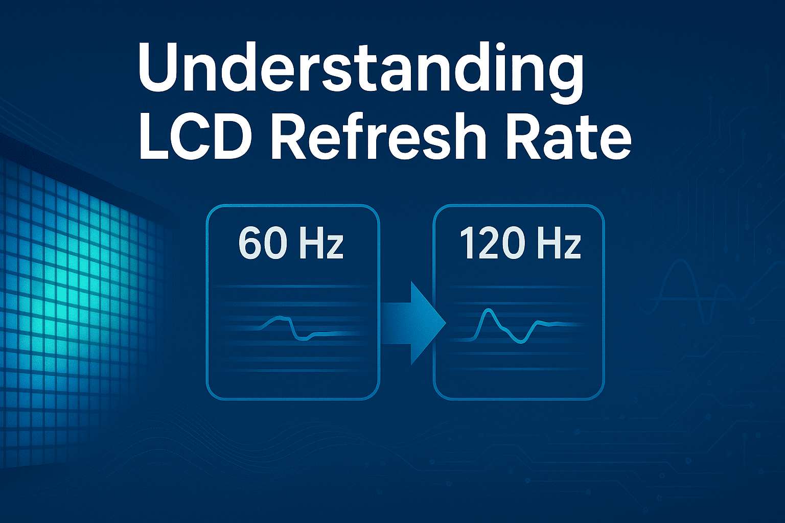
Refresh rate means how many times per second the LCD updates the image on the screen.
It is measured in hertz (Hz) — for example:
- 60 Hz → the display refreshes 60 times per second
- 120 Hz → 120 times per second
Even though the image may not always visibly change, the panel still refreshes its pixels at that rate. A higher refresh rate usually gives smoother motion and less flicker.
Key Parameters That Affect LCD Refresh Rate
- Interface Bandwidth / Pixel Clock (DCLK or DOTCLK)
- This is the most important factor.
- The pixel clock defines how fast pixel data are transmitted from the driver (MCU, GPU, or controller) to the LCD module.
- Formula (approx.):

Where

Example:
let’s go step by step with a 7.0″ TFT display (1024 × 600 resolution) and compare 16-bit RGB vs 24-bit RGB interface.
Step A. Basic Display Parameters
| Item | Symbol | Typical Value |
| Active pixels (horizontal) | H_active | 1024 |
| Active pixels (vertical) | V_active | 600 |
| Horizontal blanking (porch + sync) | H_blank | 32 |
| Vertical blanking (porch + sync) | V_blank | 23 |
| Total horizontal pixels | H_total | 1024 + 32 = 1056 |
| Total vertical pixels | V_total | 600 + 23 = 623 |
So total pixels per frame:
A 1024×600 TFT with a 40 MHz pixel clock →
Step B. Set Target Refresh Rate (e.g., 60 Hz)
We want:
Then pixel clock must be:
Conclusion: Roughly a 40 MHz dot clock is needed for 60 Hz refresh.
Step C. Calculate Data Bandwidth
Case A: 16-bit RGB (RGB565)
Each pixel = 16 bits = 2 bytes
≈ 79 MB/s
Case B: 24-bit RGB (RGB888)
Each pixel = 24 bits = 3 bytes
≈ 118 MB/s
Step D. Compare
| Parameter | 16-bit RGB | 24-bit RGB | Difference |
| Bits per pixel | 16 | 24 | +50% |
| Bandwidth needed | 632 Mbps | 948 Mbps | +50% |
| *Refresh rate (if pixel clock fixed at 40 MHz) | 60 Hz | ~40 Hz | ↓ 33% |
| Color quality | 65 K colors | 16.7 M colors | ↑ massively |
*At any fixed interface bandwidth, 24-bit needs 50% more bandwidth than 16-bit, so its achievable refresh rate is 2/3 of 16-bit’s (if everything else is equal).
Step E. Critical Thinking:
- The refresh rate is limited by the pixel clock (DCLK).
- If your LCD controller has a fixed bandwidth, using 24-bit RGB means you must lower the refresh rate or use a faster clock / better interface (e.g. LVDS, MIPI-DSI).
- For small embedded systems, 16-bit RGB is often chosen because it maintains 60 Hz refresh without needing a high-speed interface.
- Resolution (number of pixels)
- Higher resolution = more pixels to refresh → requires a higher pixel clock to keep the same frame rate.
- For example, 800×480 needs less bandwidth than 1920×1080 for the same refresh rate.
- Color Depth (Bits per Pixel)
- 24-bit RGB (8 bits per color) transfers 50% more data than 16-bit RGB, so it may limit maximum refresh rate if bandwidth is fixed.
- Interface Type
- Parallel RGB (DOTCLK) — refresh rate directly tied to pixel clock.
- LVDS, eDP, MIPI-DSI — higher data rate interfaces that allow higher refresh rates.
- SPI/MCU Interface — limited bandwidth, usually for lower resolution displays.
- Panel Response Time
- Response time is how fast the liquid crystal changes state (in milliseconds).
- Even if the refresh rate is high, slow response time can cause motion blur.
| Parameter | Impact on Refresh Rate | Notes |
| Pixel Clock (DCLK) | Directly determines refresh rate | Higher clock = faster refresh |
| Resolution | Inversely proportional | More pixels = lower refresh if clock fixed |
| Color Depth | Affects data throughput | Higher bit depth = slower if bandwidth limited |
| Interface Type | Sets max possible rate | SPI ≪ RGB ≪ LVDS/MIPI |
| Response Time | Doesn’t change refresh rate but affects motion clarity | Measured in ms |
The relationship between refresh rate and refresh time is inversely proportional. As the refresh rate increases, the duration of each frame period decreases, allowing images to be updated more frequently. Table 1 below illustrates this relationship for several common refresh rate values used in LCD panels.
Table 1. Relationship Between Refresh Rate and Frame Refresh Time
| Refresh Rate (Hz) | Frame Time (milliseconds) | Explanation |
| 30 Hz | 33.33 ms | Each image is displayed for one-thirtieth of a second; suitable for static or low-motion displays. |
| 60 Hz | 16.67 ms | Standard rate for most consumer LCDs; offers good balance between smoothness and power efficiency. |
| 90 Hz | 11.11 ms | Provides noticeably smoother motion; used in high-end smartphones and VR headsets. |
| 120 Hz | 8.33 ms | Common for gaming and automotive displays requiring fast motion response. |
| 240 Hz | 4.17 ms | Enables extremely fluid motion; mainly used in professional gaming monitors and advanced prototypes. |

From a performance standpoint, higher refresh rates improve motion fluidity and reduce flicker, resulting in a more stable and comfortable viewing experience. Applications such as gaming, augmented reality, and high-speed instrumentation often benefit from 120 Hz or higher operation. Conversely, static or semi-static displays operate efficiently at lower frequencies, balancing performance with energy savings. Adaptive and variable refresh rate technologies now dynamically adjust the frequency according to displayed content, achieving both visual stability and power optimization.
In summary, the refresh rate embodies a complex interaction between optical materials, electronic architecture, and perceptual quality. Through precise control of refresh timing and signal management, LCD technology continues to evolve toward faster, more power efficient, and more adaptive display performance.
Should you have any questions about LCD’s refresh rate, please consult our engineering.
Enhanced ESD Protection and EMI Shielding for Display Modules
Key Reasons for ESD Requirements for Displays Becoming Increasingly Common
-
Electronic Components Are Becoming More Precise and Sensitive
As technology advances, the internal components of displays—such as integrated circuits (ICs), driver chips, and touch panels (TP)—are becoming more miniaturized and low-power. This makes them less tolerant to electrostatic discharge (ESD), where even a small static charge can cause functional abnormalities, shorten the lifespan, or directly damage the components.
-
Applications Are Becoming More Diverse and Complex
Display usage has expanded beyond traditional indoor environments to more demanding settings, such as:
- Industrial equipment: frequent friction and dust accumulation easily generate static electricity
- Medical devices: require high reliability and safety
- Automotive systems: enclosed environments easily lead to electrostatic induction
- Outdoor terminals: dry climates increase the risk of static charge build-up
-
Widespread Use of Touch Technology
As touch displays become more common, users frequently interact directly with the screen. In dry environments or when wearing synthetic fabrics, it is easy to generate static electricity. Discharge directly onto the touch surface poses a greater risk to circuit integrity, so enhancing surface-level ESD protection is essential.
Our standard TFT displays typically meet the following ESD protection levels:
- Air discharge: ±8KV
- Contact discharge: ±4KV
These are in line with the specifications described in our datasheets and are essential for ensuring product reliability.

-
With increasing application demands and evolving environmental challenges, higher Electrostatic Discharge (ESD) protection levels are often required for display modules
particularly in industrial, automotive, and outdoor settings. When customers request enhanced ESD performance, such as:
- Air Discharge: ±15KV
- Contact Discharge: ±8KV
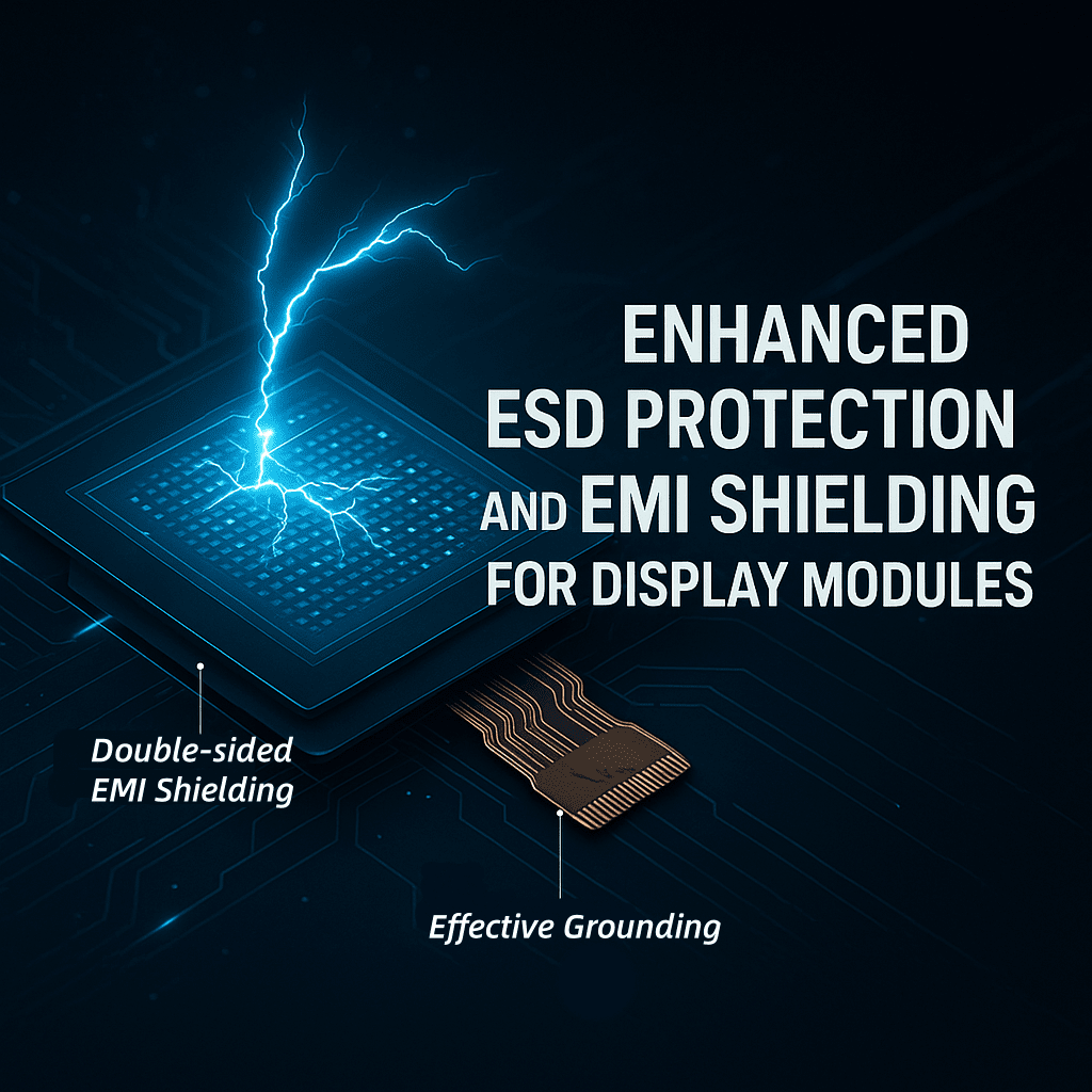
Recommended Solution: Double-sided EMI Shielding
Component: FPC Shielding Layer
Structure: Double-sided EMI (Electromagnetic Interference) Shielding Film
Description:
To improve the Electromagnetic Compatibility (EMC) of the display module, we recommend the use of a Double-sided EMI shielding structure. This design involves applying EMI shielding materials to both the front and back sides of the display module.
Key Functions:
- Effectively suppresses internal and external electromagnetic interference
- Enhances the stability and reliability of signal transmission
- Helps meet higher ESD immunity levels as specified in IEC 61000-4-2 standards

Additional Recommendations
In addition to the EMI shielding layer, further system-level measures can be considered
- Grounding design optimization between module and enclosure
- Use of conductive foam or gasket around the module perimeter
- Application of anti-static coatings or films on exposed surfaces
EMI shielding material is like an “umbrella” that blocks interference.
Grounding wire is like a “drainpipe” that channels interference away.
Only by combining both can we achieve a true “shielding + discharge” integrated protection.
Examples of Common Grounding Methods:
| Application Area | Grounding Method |
| LCM metal backplate | Connected to the mainboard GND point |
| Touch FPC shielding layer | Grounded via GND pin or metal frame |
| Conductive foam/tape | Attached to grounding copper foil or metal housing |
| EMI shielding sticker | Connected to grounding point on housing or bracket |
Signal Ground vs. Chassis Ground
Although both are referred to as “ground,” Signal Ground and Chassis (Physical) Ground have different purposes and characteristics in electronics:
Signal Ground (Logic Ground)
Purpose: Serves as a voltage reference for signal transmission (typically 0V)
Location: Internal circuit ground used by ICs, resistors, capacitors, etc.
Characteristics:
-
- Used in logic and analog circuits
- Not necessarily connected to the earth
- Typically found in low-noise, low-current environments
Example: The GND pin of an MCU or sensor
Chassis Ground / Earth Ground
Used once the display module is integrated into the full device
Purpose:
-
- Discharge static electricity (ESD) to prevent component damage
- Reduce EMI via housing-level shielding
- Improve EMC performance through unified grounding
Example: Metal frame, conductive tape, or backlight housing grounded to the device chassis
Summary
To meet elevated ESD requirements (±15KV air / ±8KV contact), both EMI shielding and effective grounding are essential.
By combining signal-level reference grounding with chassis-level discharge pathways, and by incorporating double-sided EMI shielding, we can ensure robust protection, greater product reliability, and compliance with industrial EMC/ESD standards.
Does your project have special requirements for ESD protection? Feel free to contact our engineer at <tech@orientdisplay.com>—we’re always happy to help.
What is In-Cell Technology
Have you ever heard of in-cell touchscreen technology? If not, you might be wondering what it means.
In this blog, we will take a closer look at in-cell technology while revealing how it works and the benefits it offers.
From smartphones and tablets to human machine interfaces (HMI) and more, many touchscreens are now designed with in-cell technology.
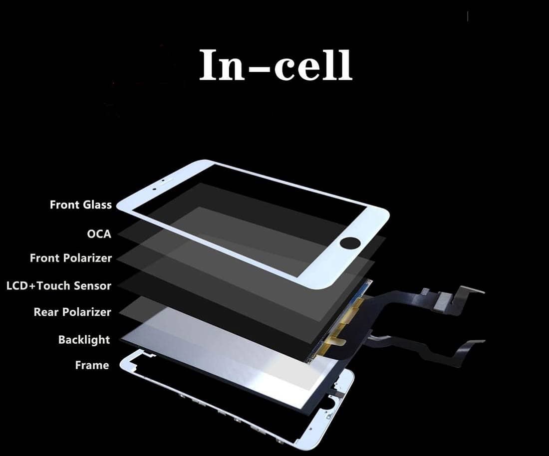
In-Cell Technology in the display industry refers to a touchscreen integration method where the touch sensors are embedded directly into the LCD or OLED display layer, eliminating the need for a separate touch layer.
Display technology has evolved rapidly in recent years. GFF, On-cell, and TDDI/IN-CELL technologies are among the most significant innovations. These technologies have reshaped the design and performance of touchscreens in various devices, including consumer electronics and industrial systems.

For more information about TDDI , please refer below link in Orient Display Blogs section:
https://orientdisplay.com/introduction-to-embedded-touch-display-driver-chip-tddi/
Advantages & Benefits of In-cell Technology
- Slimmer, Lighter Design: Since the touch sensors are integrated into the display pixels, there is no need for additional touch panel, hence able to reducing overall thickness. In-cell technology allows for thinner displays, ideal for compact devices.
- Better Display Quality: With fewer layers, less reflection, more light passes through, improved brightness/contrast.
- Improved Touch Sensitivity & Accuracy: Direct integration reduces signal interference, leading to faster and more precise touch response.
- Cost-Efficiency: In-cell displays are cost-effective, as they reduce the need for multiple components.
- Reduce the weight of a touchscreen: Touchscreens with both a display layer and a digitizer layer weigh more than those with a single and integrated layer. It’s not a substantial difference, but the use of in-cell technology can lower the weight of a touchscreen nonetheless.
- Size and Resolution Orient Display developed, as below chart, size range from 1.9” to 12.1”, more sizes coming, pls contact with Orient Display support engineers

In-cell technologies offer thinner designs, faster touch response times, and better durability. As the demand for more compact and efficient devices continues to grow, we believe the In-cell technologies will play a crucial role in shaping the future of display and touch solutions. Understanding these innovations gives us a glimpse into the future of display technology and how it will impact various industries.
Special Screen Protector for LCD
Phantom Glass is a brand of high-end tempered glass screen protectors designed for electronic devices like smartphones, tablets, and laptops.
It is the one of the toughest, strongest glass screen protection available in the market.
Key features include:
- High-strength protection: It can withstand heavy impacts, scratches, and daily wear and tear.
- Ultra-clear transparency: It’s almost invisible, maintaining the original clarity and color of your device’s screen.
- Fingerprint and smudge resistance: It has a special coating that makes it easier to clean and keeps the screen looking fresh.
- Easy installation: Typically designed for bubble-free application.
- Perfect fit: Custom-made for different brands and models of devices.
Best-in-Class Impact Resistance
9H Surface Hardness
Phantom Glass is manufactured with ion-exchange strengthened glass, offering superior durability against impacts, scratches, and surface wear.
In rigorous testing, Phantom Glass successfully passed 10 consecutive drops from a height of 1 meter directly onto the screen, meeting stringent standards required for aerospace-grade products.
Engineered for extreme resilience, Phantom Glass ensures maximum protection and structural integrity under the most demanding conditions.
In short, Phantom Glass is designed to protect your device screen as much as possible without affecting how it looks or feels.
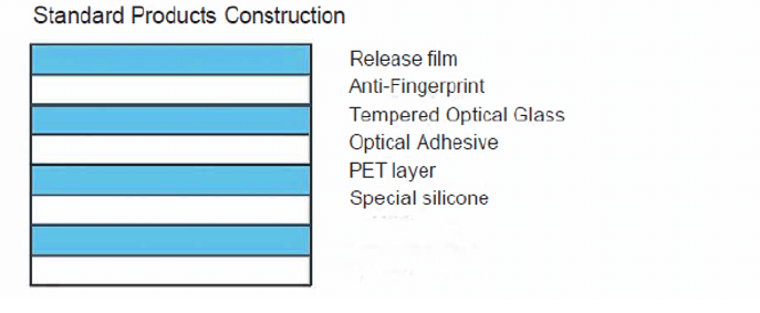
Constructions and data: