
Blog
Unique Requirements for Touch Controllers in Two-Wheeled Electric Vehicle Touch Screens
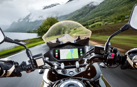
Although countless articles about the future of transportation focus on four-wheeled electric vehicles, more and more mobility rely more heavily on economical two-wheeled electric vehicles, including scooters, heavy motorcycles, electric motorcycles, e-mopeds, and e-bikes. These two-wheeled electric vehicles are following the design trends of four-wheeled electric vehicles by incorporating touchscreens for control, replacing physical knobs, buttons, and mechanical dials.
The adoption of touchscreens enables designers of two-wheeled electric vehicles to create models with a modern appearance, flexible layouts, and stylish designs. It also allows for easy customization according to different models or even individual vehicles. User-friendly menu systems can meet the more complex control, display, and functionality requirements of two-wheeled electric vehicles while also enabling value-added features such as navigation, infotainment systems, remote payments, and vehicle security.
The touchscreens on two-wheeled electric vehicles are often exposed to harsh outdoor environments, making them vulnerable to rain, snow, dust, or sand. In hot climates, these vehicles may sometimes be parked under direct sunlight, subjected to intense UV and infrared radiation. Additionally, they are prone to accidents or deliberate damage.
Considering these factors, touchscreens for two-wheeled electric vehicles should ideally have an IP65/68 protection rating and thick cover glass to safeguard the underlying touch sensors and LCD or OLED display components. To prevent damage from sunlight and UV radiation, UV/IR filters are required, and anti-reflective/anti-glare coatings should be applied to enhance screen visibility under all lighting conditions.
Consequently, the display stack needs a thick, multi-layered design. However, each additional layer increases the distance between the finger and the capacitive touch sensor, making it more challenging to accurately detect touch inputs on the screen surface.
In cold regions, touchscreens are often operated by riders wearing thick gloves, which further increases the distance between the fingers and the touch sensor. Additionally, rain or snow on the screen in wet weather can lead to false touches or missed inputs.
A high-quality touchscreen must not only reliably track the path of a finger moving across the screen but also accurately detect multi-finger gestures made with thick gloves in wet conditions, enabling functions like navigation on maps. Touchscreens need to meet a wide range of environmental demands, placing stringent requirements on the touchscreen controller IC, which must address the following design challenges:

Thicker Display Stacks
Touchscreen controllers must support significant flexibility to accommodate various layers above the touch sensor in the display stack. Advanced technology with an equivalent thickness of 10 mm or more is required, enabling the use of anti-reflective and anti-glare coatings, along with 4 mm thick cover glass and operation with 3 mm thick gloves. Alternatively, touchscreen designers may include an air gap between the screen and glass, allowing the top glass layer to be replaced without swapping the entire display in case of damage. However, the increased thickness makes it more challenging for the touchscreen controller to accurately detect and decode touch inputs. Controllers must rise to this challenge.
Reliable Touch Performance
Two-wheeled electric vehicles are typically used outdoors for most of their lifespan. Touchscreen controller algorithms must prevent water droplets from being misinterpreted as touches, detecting only inputs from fingers or gloved hands. Capacitive sensing must also distinguish between conductive cleaning solutions (like bleach) and their mixtures with water, ensuring no false touches occur.
Functional Safety
Two-wheeled electric vehicles worldwide require functional safety features to protect riders while using the touchscreen. Features like navigation and hands-free calls during riding could pose distractions. Screens may need to comply with safety standards such as ISO 26262 (ASIL-B). Controllers must provide self-testing functions, documentation, and guidelines to support certification.
Security
In rental scenarios, touchscreens may be used to input PINs, granting vehicle access to renters. They also support contactless payments via credit cards or smartphones. Touchscreen controllers must include encryption and firmware authentication to ensure data privacy.
Noise Immunity
Powertrain circuits that drive electric motors generate radiated and conducted electromagnetic noise. Switching power supply-based chargers introduce noise into vehicle power lines, and lighting systems may cause conducted noise. Even LCD or OLED panels can emit electromagnetic interference. Without proper noise control, these sources can degrade touchscreen functionality. Controllers must include noise filtering algorithms to avoid false activations, especially during operation.
Microchip’s maXTouch® Touchscreen Controllers
Microchip’s maXTouch® series is equipped with features to meet these stringent requirements and enhance the touchscreen experience. Key capabilities include:
- Support for screens from 2 to 34 inches with various aspect ratios.
- Compatibility with thick cover glass up to 10 mm and air gaps of 0.2 mm or more.
- Accurate touch detection through 5 mm thick gloves (e.g., ski or motorcycle gloves).
- Moisture resistance, preventing false touches caused by water droplets, flows, 3.5% saline, or cleaning solutions.
- Encrypted messages and hidden PIN configurations.
- Interoperability with NFC( Near Field Communication) technology.
- High conducted noise immunity (certified to Class A IEC 61000-4-6).
- Self-diagnostic and reporting functionality.
- Support for Linux®/Android™ operating systems.
Conclusion
Two-wheeled electric vehicle designs are complex, much like four-wheeled vehicles. Designers continuously add new features to meet evolving consumer expectations. Enhanced touchscreens, supported by capable touchscreen controllers, offer the flexibility required to integrate these features into vehicle designs. By addressing unique requirements and carefully selecting touchscreen controllers, the demands of two-wheeled electric vehicle designs can be effectively met.
What If a Display Screen Can’t be Light Up?
Summary of Steps to Resolve Issues When the Display Screen Won’t Turn On
Step 1:
Provide the schematic diagram and testing program. Generally, 95% of customers can light up the display screen with the information.
Step 2:
If the display still doesn’t turn on, the customer needs to determine whether the issue lies in the hardware or software. At this point, it’s best to provide the customer with a demo unit. This helps the customer confirm that the display itself is not damaged and significantly aids their troubleshooting process.
Step 3:
If the issue persists, the customer can share their schematic design and software with the factory engineers for review to identify any potential problems. This step should resolve 99% of issues.
Step 4:
If the display still doesn’t turn on after the previous steps, the customer can send their designed board to the factory engineers for further troubleshooting assistance.
Note: Some customers send us the MCU or evaluation kit (e.g., development board) they are using and ask us to provide design suggestions. However, this is highly challenging. The market has a vast variety of MCUs, and it is unrealistic for or engineers to be familiar with all of them.
For example, it’s similar to a scenario where our engineers are skilled at repairing Toyota cars, but a customer brings in a Tesla and asks for diagnostics. The engineers would need to spend a significant amount of time studying and understanding the new system.
Here is a detailed description of the issue:
We often receive customer emails like this:
“I have issues with getting the display to work. How can I do?”
When it comes to troubleshooting display screens that won’t turn on, the problem typically falls into two categories: hardware or software.
Hardware:
Configuration Issues
LCD screens often have many pins, and factories may have implemented specific configurations. Simply relying on the datasheet to troubleshoot can sometimes be very challenging. Customers not only need to be familiar with the LCD driver but also deal with component configurations or failures, which can sometimes drive them to frustration.
Proper documentation and detailed schematics are crucial for helping customers overcome these hardware challenges.

Since our engineers already successfully lit up the display, the simplest solution is to provide the schematic diagram of the our testing setup for the display to the customer. This makes the our approach to configuring the display and components clear at a glance.
While the customer’s MCU might differ from the one used by the factory in testing, they are often similar in functionality. Sharing this schematic helps the customer avoid unnecessary detours during troubleshooting.
The schematic typically looks like this:
When Everything Seems Correct, But the Display Still Won’t Light Up:
Sometimes, even when all configurations appear correct, the display still doesn’t turn on. This could be due to common physical issues such as:
- Display damage (e.g., from handling or manufacturing defects).
- FPC (Flexible Printed Circuit) tearing, which disrupts the electrical connection.
- Electrostatic discharge (ESD) damage, which can destroy sensitive components.
For delicate and high-precision displays, it’s recommended to keep at least two spare units on hand to avoid downtime caused by damage.
If the display still doesn’t work, the customer should consider purchasing our demo board or evaluation board. These provide a pre-tested and reliable reference design, significantly shortening the customer’s development cycle and helping them identify whether the issue lies in their setup or the display itself.
Software (Firmware)
For some displays, the configuration can be highly complex, especially with settings like register configurations. These settings often require meticulous understanding and programming, and even factory engineers may occasionally make mistakes.
The good news is that IC manufacturers typically provide example code and library files, which handle the most intricate tasks. By including the library files, engineers can streamline their workflow:
c
Copy code
#include <LibraryFile>
This allows the IC manufacturer’s pre-defined settings to be imported into the program. Afterward, engineers only need to define the interface and desired functions.
For customers unfamiliar with the ICs we use, it’s best to provide the sample code from our product testing. This helps them avoid unnecessary detours and significantly simplifies their development process.
Sample code can be provided in formats such as .txt files, .h (hexadecimal files), or other formats, all of which are useful references for the customer.
Sample code typically looks like this:

Alternatively (when using a compiler IDE)

With the above hardware and software support, 95% of customers can resolve their issues. However, some customers may still be unable to light up the display. This could indicate a problem with the customer’s motherboard.
Supporting the customer’s motherboard is challenging for the factory, mainly because of the vast variety of controllers they use. Factory engineers would need to invest significant time in thoroughly studying the customer’s controller and PCB wiring.
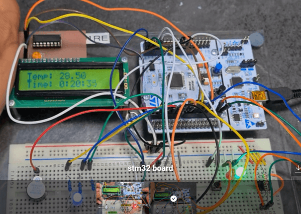
That said, if the factory engineers are familiar with commonly used controllers, such as the 51 series, STM32 series, or Arduino series, they may be able to assist.
If the factory engineers have knowledge of the customer’s MCU, they can provide targeted support by offering:
- The connection method between the MCU and the LCD (as shown in the diagram below).
- Corresponding sample code for the specific setup.

Note:
- Difference Between Demo Board and Evaluation Board (Evaluation Kit):
- Demo Board:
Designed specifically for demonstrating display functionality by the factory. Customers cannot, or find it difficult to, modify the images or display configurations. - Evaluation Board:
More flexible as it allows customers to program and upload their own images, or even modify display settings. Currently, we offer two affordable evaluation boards:- JAZZ-MCU-01:
Designed to drive displays with SPI, I2C, 8-bit, or 16-bit MCU/TTL interfaces. The factory can pre-load images provided by the customer, or if the customer is familiar with AGU’s products, they can upload their own images. - JAZZ-HDMI-01:
Designed to drive displays with RGB, LVDS, or MIPI interfaces. Since it uses HDMI, customers can connect it to a computer to view their desired images and videos directly.
- JAZZ-MCU-01:
- Demo Board:
- Difference Between Software (Code) and Firmware:
- Firmware:
Firmware is also code but is used at the hardware’s lower levels. It typically involves fundamental hardware settings that are rarely changed. For example, in touch control ICs, factory-set firmware often includes settings like touch sensitivity and temperature curves. - Code (Software):
Built on top of the firmware, software enhances the hardware’s functionality by implementing advanced features. It allows for user-specific customization and higher-level operations.
- Firmware:
Introduction to Embedded Touch Display Driver Chip (TDDI)
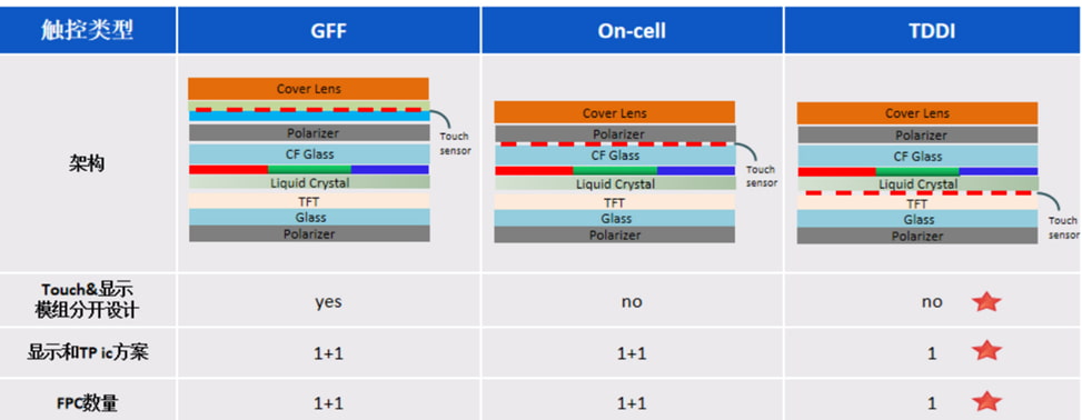
TDDI (Touch and Display Driver Integration) technology combines touch functionality with the display driver in a single chip, simplifying the display structure and enhancing performance. In TDDI technology, the touch sensor is typically integrated directly into the glass substrate of the display panel, creating an all-in-one touch and display solution.
Specifically, TDDI technology embeds the touch sensor between the color filter substrate and the polarizer of the display screen, positioning the touch sensor within the glass layer of the display. This high level of integration enables both display and touch functionality in a streamlined form. This design makes the display thinner, reduces bezel width, improves the screen-to-body ratio, and simplifies the supply chain. The structure is as follows:

- The GFF (Glass-Film-Film) solution uses a separate structure for display and touch, where display and touch are independent modules.
- The On-cell solution embeds the touch sensor between the color filter substrate and the polarizer of the display screen, positioning the touch sensor on the display glass. This merges the display and touch modules into one, but the IC and FPC remain separate with two distinct designs.
- The TDDI solution fully integrates the touch sensor into the display’s TFT panel, unifying the display and touch modules, IC, and FPC into a single design. This is a highly integrated solution for display and touch functionality.
Due to its high level of integration, the TDDI solution offers benefits such as a thinner display, cost reduction, and a simplified supply chain. It has become the mainstream solution for LCD screens in smartphones. As of 2020, the LCD TDDI solution has accounted for over 50% of applications in smartphone display and touch functionality.
The development trends in smartphone TDDI display technology include high refresh rates, narrow bezels, and high functional integration.
(1) Advantages of High Refresh Rates
- Reduces flickering and jitter in image display, which helps alleviate eye strain.
- Enhances dynamic scenes in gaming applications, reducing blur and screen tearing during fast movements.
- Improves smoothness during screen transitions or scrolling, minimizing blurriness and ghosting in images and videos.
Requirements for TDDI IC: To support high refresh rates, TDDI ICs need faster MIPI data reception, higher oscillation frequencies (OSC), stronger drive capabilities, and faster response and processing speeds.

FHD LTPS TDDI: Production for 144Hz displays has been achieved, but 160Hz is still in the initial RFI (Request for Information) stage, with no corresponding products yet. Additionally, demand for LCD TDDI at 160Hz remains unclear, so most manufacturers are adopting a wait-and-see approach.
HD a-Si TDDI: Production has reached 90Hz, and a new recessed bump IC now supports 120Hz. For HD 120Hz displays, there are no technical bottlenecks or additional costs. Once cost-compatible motherboard configurations become available, manufacturers plan to launch projects, potentially upgrading HD displays to 120Hz.
(2) Narrow Bezels and Ultra-Narrow Bottom Bezels for Full-Screen Design
Manufacturers are also pursuing ultra-narrow bezels, especially at the bottom, to achieve a truly full-screen experience.

Narrow Bezel Technology Solutions:
- Pad Arrangement:
The interlace arrangement, compared to the no-interlace design, can reduce the bottom bezel by about 1mm without additional cost or performance impact. Thus, since 2017, interlace has replaced no-interlace as the mainstream choice. - Bonding Type:
The COF (Chip on Film) solution offers an advantage over COG (Chip on Glass) in terms of achieving narrower bezels. However, COF increases costs, making it less suitable for mid-to-low-end LCD models. Therefore, COG remains the primary bonding type for LCD TDDI solutions. - Gate Design:
Between 2018 and 2019, display and IC manufacturers introduced the dual gate design for HD a-Si displays to achieve narrower bottom bezels. However, as the dual gate design had performance issues and conflicted with the high refresh rate trend that emerged in late 2019, the market quickly abandoned it. Currently, the traditional single gate design dominates TDDI for smartphones. - Bump Design:
Following the discontinuation of the dual gate approach, glass manufacturers proposed a new recessed bump design to achieve narrower bezels. This design adds no extra cost and has no impact on other performance areas. It is expected to gradually replace the standard normal bump design, becoming the mainstream approach.
FHD LTPS: With a source demux design, the bottom bezel in the traditional normal bump configuration is already around 3.1mm. The reduction achieved by switching to recessed bump is minimal, so the demand for this change is not strong, and it remains in pre-research.
HD a-Si: The traditional normal bump design has a bottom bezel of 4.0-4.2mm, while the recessed bump design can reduce it to 3.0-3.2mm, achieving approximately a 1mm reduction. This approach is prioritized for HD products and is already in production for some smartphone models. Large-scale production is anticipated in the second half of 2022, with recessed bump expected to gradually replace normal bump as the mainstream solution.
Here are some major manufacturers of TDDI (Touch and Display Driver Integration) chips and examples of their products:
- Novatek:
- NT36525: Supports high-resolution displays, suitable for smartphones and tablets.
- NT36523: Designed for mid-to-high-end smartphones, featuring high refresh rates.
- FocalTech:
- FT8756: Supports Full HD (FHD) resolution, suitable for smartphones.
- FT8751: A cost-effective option for mid-to-low-end devices.
- Himax:
- HX8399: Supports high-resolution displays, suitable for smartphones and tablets.
- HX8394: Suitable for mid-range smartphones with good display performance.
- Solomon Systech:
- SSD2010: Supports a 454RGBx454 resolution, ideal for wearable devices.
- Chipone:
- ICNL9911C: Supports HD/HD+ resolution, suitable for smartphones.
- TDYTech:
- TD4160: Supports high refresh rates and multi-finger touch, suitable for smartphones and tablets.
- Synaptics:
- TD4303: Supports hybrid in-cell panel technology, suitable for smartphones.
These TDDI chips are widely used in smartphones, tablets, and wearable devices, offering high integration and excellent display and touch performance.
If you have any questions about Display and Touch Waterproofing Requirements, please contact Orient Display support engineers
Introduction to Cover Glass for Displays
Cover Glass (Cover Lens) is primarily used as the outermost layer of touch screens. The main raw material for these products is ultra-thin flat glass, which offers features such as impact resistance, scratch resistance, oil and fingerprint resistance, and enhanced light transmittance. It is currently widely used in various electronic consumer products with touch and display functionalities.
1. Classification of Glass
a. Soda-lime glass: Primarily composed of SiO₂, with additional content of 15% Na₂O and 16% CaO.
b. Aluminosilicate glass: Mainly composed of SiO₂ and Al₂O₃.
c. Quartz glass: Contains more than 99.5% SiO₂.
d. High-silica glass: Contains approximately 96% SiO₂.
e. Lead-silicate glass: Mainly composed of SiO₂ and PbO.
f. Borosilicate glass: Primarily made up of SiO₂ and B₂O₃.
g. Phosphate glass: Mainly composed of phosphorus pentoxide (P₂O₅).
Types c through g are rarely used in displays, so they will not be discussed here.
2. Processing Techniques for Glass Raw Materials
a. Float Glass
Float glass is produced using raw materials such as sea sand, quartz sandstone powder, soda ash, and dolomite. These materials are mixed and melted at high temperatures in a furnace. The molten glass continuously flows from the furnace and floats on the surface of a molten metal bath, forming a uniformly thick, flat glass ribbon that is flame-polished. After cooling and hardening, the glass separates from the molten metal, and it is then annealed and cut to create transparent, colorless flat glass. The forming process of float glass is completed in a tin bath with protective gas, resulting in a distinction between the tin side and the air side of the glass.

b. Overflow Process:
In the overflow process, molten glass enters the overflow channel from the feeder section and flows downward along the surface of a long overflow trough. The glass converges at the bottom tip of a wedge-shaped body under the overflow trough, forming a glass ribbon. After annealing, this process creates flat glass. This method is currently a popular technique for manufacturing ultra-thin cover glass, offering high processing yield, good quality, and overall excellent performance. Unlike float glass, overflow glass does not have a tin side or an air side.

3. Introduction to Soda-Lime Glass
a. Also known as soda glass (English: soda-lime glass), it is processed using the float method, hence also called float glass. Due to the presence of a small amount of iron ions, the glass appears green when viewed from the side, and is therefore also referred to as green glass.
b. Thickness of Soda-Lime Glass: 0.3–10.0 mm
c. Brands of Soda-Lime Glass:
- Japanese brands: Asahi Glass Co. (AGC), Nippon Sheet Glass Co. (NSG), Central Glass (CENTRAL), etc.
- Chinese brands: CSG Holding, Xinyi Glass, Luoyang Glass, AVIC Sanxin, Jinjing Group, etc.
- Taiwanese brand: Taiwan Glass (TGC).
4. Introduction to High Aluminosilicate Glass (High Alumina Glass)
a. Brands of High Alumina GlassUnited States: Corning Gorilla Glass, an eco-friendly aluminosilicate glass produced by Corning Incorporated.Japan: Dragontrail Glass, produced by AGC Inc. This glass is commonly referred to as “Dragontrail Glass.”China: Panda Glass, produced by Xuhong Company, is a high alumina glass. Other manufacturers include CSG Holding and Kibing Group.
b. Cover Glass ProcessingCompanies involved in processing cover glass include Lens Technology, Boen Optics, Shenzhen Xinhao, G-Tech Optoelectronics, Jiangxi Firstar , BYD, and others.
5. Chemical Strengthening of Glass
a. Principle:
The glass is immersed in a molten salt bath (KNO₃). The high concentration of K⁺ ions penetrates the glass surface and replaces the Na⁺ ions within the glass. Since the ionic radius of K⁺ is larger than that of Na⁺, this substitution increases the surface density of the glass, generating compressive stress on the surface. This process enhances the glass’s strength through chemical reinforcement.

b. Test Items for Chemical Strengthening
Depth of Layer (DOL): Indicates the depth of the stress layer after the glass has been strengthened.
Compressive Stress (CS): Represents the surface compressive stress of the chemically strengthened glass.
Surface Hardness: Evaluated using a pencil hardness test.
Drop Ball Test: A destructive test to assess the glass’s impact resistance.

Note:
- Based on our project experience, we recommend the following: a. Use 1.1 mm thick glass for IK04.b. Use 1.8 mm thick glass for IK06.c. Use 3.0 mm thick glass for IK08.d. Use 6.0 mm thick glass for IK10.
- Physically tempered glass is mainly recommended when safety is a priority for the customer. This is because, when broken, physically tempered glass shatters into small granular pieces, unlike chemically tempered glass, which can break into sharp shards, posing a safety hazard.
- For chemically strengthened glass, to enhance safety, optical bonding or applying an anti-shatter film to the surface can prevent glass fragments from scattering upon breakage.
6. Production Process Flow for Glass Cover Lens
Cutting → CNC (shaping, drilling, edging, and chamfering) → Ultrasonic Cleaning → Chemical Strengthening → Ultrasonic Cleaning → Full Inspection of Blank Glass → Screen Printing → Baking → Full Inspection of Glass → Ultrasonic Cleaning → Surface AR Coating → AF Anti-Fingerprint Coating → Full Inspection of Glass → Film Coating and Packaging.
Key steps are explained as follows:
a. Cutting
The original glass sheet is cut with a diamond wheel cutter and then snapped into rectangular pieces that are 20-30 mm larger on each side than the final product dimensions.
b. CNC (Shaping, Drilling, Edging, and Chamfering)
Using high-hardness diamond grinding wheels rotating at high speed, the glass substrate undergoes mechanical grinding under excellent cooling and lubrication conditions to achieve the desired structural dimensions. Different tool shapes and grit sizes are designed to meet various processing requirements.
c. Chemical Strengthening
At high temperatures, an ion exchange occurs between the glass and KNO₃, where ions from KNO₃ replace the ions in the glass. Due to the larger atomic radius of the replacement ions, the surface of the glass undergoes compressive stress after tempering. When the glass is subjected to external force, this compressive layer can offset some of the tensile stress, preventing the glass from breaking. This compressive stress increases the glass’s resistance to bending and impact. Factors affecting the strength performance of chemically tempered glass (such as drop ball tests and four-point bending tests) include: 1) Tempering performance indicators of the glass (DOL, CS); 2) Internal and surface defects of the glass (micro-cracks and scratches); 3) Edge chipping and hidden damage formed during CNC processing; 4) Inherent defects in the glass raw material (impurities in the raw material, uneven areas, air bubbles, and inclusions, which are uncontrollable factors).
d. Polishing
The glass material is ground and polished using a double-sided grinder equipped with polishing pads and polishing powder. This process removes surface impurities and micro-cracks, enhancing the glass’s surface smoothness and reducing roughness. The main component of the polishing powder is cerium oxide. Cerium oxide polishing powder particles are polygonal with distinct edges, having an average diameter of about 2 microns and a hardness of Mohs 7-8. The particle size and purity of cerium oxide polishing powder directly affect the polishing outcome.
e. Ultrasonic Cleaning
When high-frequency vibrations (28–40 kHz) are transmitted to the cleaning medium, the liquid medium generates nearly vacuum-like cavitation bubbles. As these bubbles collide, merge, and dissipate, they create localized pressure bursts of several thousand atmospheres within the liquid. Such high pressure causes surrounding materials to undergo various physical and chemical changes, a process known as “cavitation.” Cavitation can break chemical bonds in material molecules, leading to physical changes (dissolution, adsorption, emulsification, dispersion) and chemical changes (oxidation, reduction, decomposition, synthesis), effectively removing contaminants and cleaning the product.
f. Printing
The principle of printing involves creating a stencil using photosensitive materials. Ink is placed in the screen frame, and a squeegee applies pressure to push the ink through the screen mesh openings onto the substrate, forming patterns and text identical to the original design.
g. Coating
Under vacuum conditions (10⁻³ Pa), an electron gun emits a high-speed electron beam to bombard and heat the coating material, causing it to evaporate and deposit onto the substrate surface, forming a thin film. Coating equipment primarily consists of a vacuum system, an evaporation system, and a film thickness monitoring system. Common coatings include functional films like AF (anti-fingerprint), AR (anti-reflective), AG (anti-glare), high-hardness films, decorative films such as NCVM (Non-Conductive Vacuum Metallization), and iridescent films.
7. IK Rating
IK ratings are an international classification that indicate the degree of protection provided by electrical enclosures against external mechanical impacts.
IK ratings are defined as IK00 to IK10. The IK rating scale identifies the ability of an enclosure to resist impact energy levels measured in joules (J) in accordance with IEC 62262 (2002).
IEC 62262 specifies how the enclosure must be mounted for testing, the atmospheric conditions required, the quantity and distribution of the test impacts and the impact hammer to be used for each level of IK rating. The test is carried out by a Charpy pendulum impact tester.
IK00 Not protected
IK01 Protected against 0.14 joules impact.
Equivalent to impact of 0.25 kg mass dropped from 56 mm above impacted surface.
IK02 Protected against 0.2 joules impact.
Equivalent to impact of 0.25 kg mass dropped from 80 mm above impacted surface.
IK03 Protected against 0.35 joules impact.
Equivalent to impact of 0.25 kg mass dropped from 140 mm above impacted surface.
IK04 Protected against 0.5 joules impact.
Equivalent to impact of 0.25 kg mass dropped from 200 mm above impacted surface.
IK05 Protected against 0.7 joules impact.
Equivalent to impact of 0.25 kg mass dropped from 280 mm above impacted surface.
IK06 Protected against 1 joules impact.
Equivalent to impact of 0.25 kg mass dropped from 400 mm above impacted surface.
IK07 Protected against 2 joules impact.
Equivalent to impact of 0.5 kg mass dropped from 400 mm above impacted surface.
IK08 Protected against 5 joules impact.
Equivalent to impact of 1.7 kg mass dropped from 300 mm above impacted surface.
IK09 Protected against 10 joules impact.
Equivalent to impact of 5 kg mass dropped from 200 mm above impacted surface.
IK10 Protected against 20 joules impact.
Equivalent to impact of 5 kg mass dropped from 400 mm above impacted surface.
If you have any questions about Display Cover Glass, please contact Orient Display support engineers
The analysis of Waterproof Requirements for Touch and Displays
Normally, for our display screens, when a customer mentions waterproofing, we need to clarify which part of the display needs to be waterproof.
The product needs to be waterproof. This requirement is generally for products with touchscreens. The waterproofing of the back of the display relies on the customer’s housing. We mainly focus on the sealing between the cover plate and the customer’s housing, as well as the sealing at the junction between the touchscreen and the display.
- The touchscreen cover plate needs to be waterproof when assembled into the customer’s product. This requirement is quite common, and customers often have specific data requirements for sealing, such as an IP rating – grading the resistance of an enclosure against the intrusion of dust or liquids. In this case, we only need to choose the appropriate 3M double-sided tape to achieve the desired result. If no touch panel in the design, the polarizer will not resist long term water corrosion. Apply an acrylic protective layer on top of the display screen and securely adhere it with glue.
- The area between the display screen and the touchscreen needs to be waterproof. Although some of our touchscreens are bonded to the display with OCA, the sensor part is still exposed. Therefore, it is necessary to use RTV sealant to seal the perimeter around the bonding area between the touchscreen and the TFT.
- Waterproof Touchscreen Functionality. In some cases, customers may use the touchscreen while water droplets are present. The touchscreen needs to function properly in the presence of water droplets (normal touch function with water/no false touches from falling water droplets). For this situation, it is necessary to select an appropriate touch IC and special sensor design to ensure better reliability.
- Waterproof PCB. Sometimes customers require the PCB to be waterproof. In this case, it is necessary to add a layer of Conformal Coating on the PCB. This involves applying a transparent polymer film over the PCB, which maintains the shape of the printed circuit board and protects the electronic components on the PCB from environmental damage, thereby improving and extending their lifespan. For more severe weatherproofing requirements, the entire circuit board is fully encapsulated in glue, effectively immersing the board in the adhesive. It is essential that this glue is neutral, without any acidic or alkaline properties, to prevent corrosion of the components.
- Housing Assembly. After assembling the casing, apply sealant to the seams of the casing to ensure that the entire hardware part is airtight. However, even with these measures, it cannot be guaranteed that no water vapor will penetrate, as water molecules are very pervasive. The goal is to minimize the ingress as much as possible. Incorporate breathable vents like Gore vents that allow air to pass through but block water and moisture. Sometimes, utilizing laser welding for creating precise and strong seals in the device’s casing.
- Other Waterproofing Ideas
- Potting: Apply potting compounds around connectors and cables to seal any potential entry points.
- Sealed Connectors: Use waterproof connectors and cables to prevent moisture ingress at connection points.
- Incorporation of Desiccants: Place desiccants inside the device to absorb any residual moisture.
IP Rating — IP XX
The two digits following IP indicate the level of protection that the device’s enclosure provides against the ingress of solid objects and water. The first digit represents the level of protection against dust and foreign objects, while the second digit indicates the level of moisture and water resistance. The higher the number, the greater the level of protection.
For example, an IP rating of IP54:
- IP: Designates the protection marking.
- 5: The first digit indicates the level of protection against contact and foreign objects.
- 4: The second digit indicates the level of protection against water.
The first digit (5) signifies a level of protection against dust and limited ingress of particles. The second digit (4) signifies a level of protection against water splashes from any direction.
Dust Protection Level
The first digit in the IP rating system represents the level of protection against solid objects, including dust. Here are the possible levels:
- 0: No protection against contact and ingress of objects.
- 1: Protection against solid objects over 50 mm (e.g., accidental touch by hands).
- 2: Protection against solid objects over 12.5 mm (e.g., fingers).
- 3: Protection against solid objects over 2.5 mm (e.g., tools, thick wires).
- 4: Protection against solid objects over 1 mm (e.g., most wires, screws).
- 5: Limited protection against dust ingress (no harmful deposits).
- 6: Complete protection against dust ingress.
Water Protection Level
The second digit in the IP rating system indicates the level of protection against the ingress of water. Here are the possible levels:
- 0: No protection.
- 1: Protection against vertically dripping water.
- 2: Protection against dripping water when tilted up to 15 degrees.
- 3: Protection against spraying water at an angle up to 60 degrees.
- 4: Protection against splashing water from any direction.
- 5: Protection against water jets from any direction.
- 6: Protection against powerful water jets.
- 7: Protection against immersion in water up to 1 meter depth.
- 8: Protection against continuous immersion in water beyond 1 meter.
IP Rating Explanation for Immersion
- 7: The device can be immersed in water under specified pressure for a specified time, ensuring that the amount of water ingress does not reach harmful levels.
- 8: The device can be continuously immersed in water under conditions agreed upon by the manufacturer and the user, typically more stringent than those of IP67.
ISO 16750 and Other International Standards:
- Scope
The waterproof tests include the second characteristic digits from 1 to 8, corresponding to protection levels IPX1 to IPX8.
- Waterproof Test Content for Various Levels
(1) IPX1
- Method Name: Vertical Drip Test
- Test Equipment: Drip test device and its test method
- Sample Placement: Place the sample in its normal working position on a rotating sample table at 1 rotation per minute (r/min). The distance from the top of the sample to the drip outlet should not exceed 200mm.
- Test Conditions:
- Drip rate: 1.0 +0.5 mm/min
- Test duration: 10 minutes
(2) IPX2
- Method Name: Tilted Drip Test
- Test Equipment: Drip test device and its test method
- Sample Placement: Tilt the sample 15 degrees from its normal working position, in four fixed positions, one for each tilted direction.
- Test Conditions:
- Drip rate: 3.0 +0.5 mm/min
- Test duration: 2.5 minutes per tilt direction (total 10 minutes)
(3) IPX3
- Method Name: Spraying Water Test
- Test Equipment: Oscillating spray test device or spray nozzle
- Sample Placement: Place the sample in its normal working position.
- Test Conditions:
- Spray water at an angle up to 60 degrees from vertical.
- Water flow rate: 10 liters per minute.
- Test duration: 5 minutes.
(4) IPX4
- Method Name: Splashing Water Test
- Test Equipment: Oscillating spray test device or spray nozzle
- Sample Placement: Place the sample in its normal working position.
- Test Conditions:
- Splash water from all directions.
- Water flow rate: 10 liters per minute.
- Test duration: 5 minutes.
(5) IPX5
- Method Name: Water Jet Test
- Test Equipment: Nozzle with a 6.3mm diameter
- Sample Placement: Place the sample in its normal working position.
- Test Conditions:
- Water jet flow rate: 12.5 liters per minute.
- Distance: 2.5 to 3 meters.
- Test duration: 3 minutes per square meter for at least 3 minutes.
(6) IPX6
- Method Name: Powerful Water Jet Test
- Test Equipment: Nozzle with a 12.5mm diameter
- Sample Placement: Place the sample in its normal working position.
- Test Conditions:
- Water jet flow rate: 100 liters per minute.
- Distance: 2.5 to 3 meters.
- Test duration: 3 minutes per square meter for at least 3 minutes.
(7) IPX7
- Method Name: Immersion Test
- Test Equipment: Water tank
- Sample Placement: Submerge the sample in water.
- Test Conditions:
- Depth: 1 meter.
- Test duration: 30 minutes.
(8) IPX8
- Method Name: Continuous Immersion Test
- Test Equipment: Water tank
- Sample Placement: Submerge the sample in water under conditions agreed upon by the manufacturer and user.
- Test Conditions:
- Depth: Generally deeper than IPX7, specific conditions defined by agreement.
- Test duration: Typically longer than IPX7, as agreed upon.
These tests ensure that the devices meet specific standards for waterproofing based on their intended use and environmental conditions.
If you have any questions about Display and Touch Waterproofing Requirements, please contact Orient Display support engineers
Analysis of Display and Touch Waterproofing Requirements
For our display screens, when customers mention waterproofing, it’s important for us to understand which specific parts they require to be waterproof.
- The product needs to be waterproof. This usually applies to products with touch screens, where the backside waterproofing of the display screen relies on the customer’s external casing to ensure. Our main considerations lie in sealing the cover plate and the customer’s casing, as well as sealing the interface between the touch screen and the display screen.
- The touch screen cover assembly onto the customer’s product needs to be waterproof. This requirement is quite common, and customers often have specific data requirements for sealing, such as an IP rating, which grades the resistance of an enclosure against the intrusion of dust or liquids. In this case, we only need to select the appropriate 3M double-sided adhesive to achieve the desired waterproofing.
- Waterproofing is required between the display screen and the touch screen. Although some of our touch screens are optically clear adhesive (OCA) bonded to the display screen, the sensor part remains exposed. Therefore, it is necessary to use RTV sealant to seal the periphery of the bond between the touch screen and TFT (thin-film transistor) display.
- Waterproofing for touch screen functionality:
In some cases, customers may use the touch screen in environments where water droplets are present. In such situations, the touch screen should be able to function normally even with water droplets present (ensuring normal touch functionality with water present and preventing accidental touches from falling water droplets). In this scenario, it’s necessary to select appropriate ICs for better water or salt water stability.
- Waterproofing for PCBs:
Sometimes, customers request waterproofing for PCBs. In such cases, the solution typically involves adding a layer of conformal coating (also known as three-proof paint) onto the PCB. This coating is a transparent polymer film applied to the PCB, maintaining the shape of the printed circuit board while protecting the electronic components from environmental damage. This process enhances and prolongs their usability.
IP Rating — IP XX
The two digits following “IP” indicate the device’s enclosure’s protection against solid foreign objects and water ingress. The first digit represents the degree of protection against dust and ingress of solid foreign objects, while the second digit represents the degree of protection against moisture and water ingress. A higher number indicates a higher level of protection.
For example, in the IP54 rating, “IP” is the designation letter, “5” is the first digit indicating protection against contact and ingress of solid foreign objects, and “4” is the second digit indicating protection against water ingress.
| 1st digit | Intrusion protection | 2nd digit | Moisture protection |
| 0 | No protection. | 0 | No protection. |
| 1 | Protected against solid objects over 50mm, e.g. accidental touch by hands. | 1 | Protected against vertically falling drops of water, e.g. condensation. |
| 2 | Protected against solid objects over 12mm, e.g. fingers. | 2 | Protected against direct sprays of water up to 15 degrees from the vertical. |
| 3 | Protected against solid objects over 2.5mm, e.g. tools & wires. | 3 | Protected against direct sprays of water up to 60 degrees from the vertical. |
| 4 | Protected against solid objects over 1mm, e.g. wires & nails. | 4 | Protected against water splashed from all directions, limited ingress permitted. |
| 5 | Protected against dust limited ingress, no harmful deposits. | 5 | Protected against low pressure jets of water from all directions, limited ingress permitted. |
| 6 | Totally protected against dust. | 6 | Protected against strong jets of water, e.g. on ships deck, limited ingress permitted. |
| / | / | 7 | Ability to withstand immersion in water under specified pressure for a set duration without allowing water ingress to a level that would cause harm. |
| / | / | 8 | Under conditions agreed upon by the manufacturer and user, the product should be able to be submerged in water without reaching a harmful level of water ingress. |
ISO 16750 Standard
ISO 16750 is an international standard that specifies environmental conditions and testing for electrical and electronic equipment in road vehicles. It covers various aspects such as mechanical loads, vibrations, temperature, and humidity, among others, to ensure the reliability and durability of automotive electronic components and systems.
1. Scope
Waterproof testing includes second characteristic digits ranging from 1 to 8, corresponding to protection level codes from IPX1 to IPX8.
2. Waterproof Test Content for Various Levels:
(1) IPX1
Test Method: Vertical Drip Test
Test Equipment: Drip test device and its test method
Sample Placement: The sample is placed in its normal operating position on a rotating sample table at 1 revolution per minute (1r/min), with the distance from the sample top to the drip nozzle not exceeding 200mm.
Test Conditions: Drip rate of 1.0 ± 0.5 mm/min; Test duration: 10 minutes
(2) IPX2
Test Method: 15° Tilt Drip Test
Test Equipment: Drip test device and its test method
Sample Placement: Tilt the sample at a 15° angle from the vertical, with the distance from the sample top to the drip nozzle not exceeding 200mm. After testing one side, rotate to another side, repeating this process four times.
Test Conditions: Drip rate of 3.0 ± 0.5 mm/min; Test duration: 4 cycles of 2.5 minutes each, totaling 10 minutes.
(3) IPX3
Test Method: Rainfall Test
a. Oscillating Tube Rain Test
Test Equipment: Oscillating tube rainfall test equipment
Sample Placement: Select an appropriate radius for the oscillating tube so that the height of the sample platform is at the diameter position of the oscillating tube. Place the sample on the platform, ensuring that the distance from the top of the sample to the water spray nozzle is not greater than 200mm. The sample platform does not rotate.
Test Conditions: The water flow rate is calculated based on the number of water spray holes in the oscillating tube, with each hole at 0.07 L/min. During rainfall, water sprays from the water spray holes within a 60° arc segment on each side of the midpoint of the oscillating tube, totaling 120°. The test sample is placed at the center of the oscillating tube’s semi-circle. The oscillating tube swings 60° on each side of the vertical line, totaling 120°. Each swing (2×120°) takes approximately 4 seconds.
Test Pressure: 400 kPa; Test Duration: Continuous rainfall for 10 minutes; After 5 minutes of testing, rotate the sample 90°.
b. Nozzle Type Rain Test
Test Equipment: Handheld rainfall test equipment
Sample Placement: Position the sample so that the parallel distance from the top of the sample to the nozzle of the handheld spray is between 300mm and 500mm.
Test Conditions: During the test, a shield with balance weights should be installed. The water flow rate is set at 10 L/min.
Test Duration: The test duration is calculated based on the surface area of the test sample enclosure, with 1 minute per square meter (excluding the mounting area), and a minimum of 5 minutes.
(4) IPX4
Test Method: Water Splash Test
a. Oscillating Tube Water Splash Test
Test Equipment and Sample Placement: Select an appropriate radius for the oscillating tube so that the height of the sample platform is at the diameter position of the oscillating tube. Place the sample on the platform, ensuring that the distance from the top of the sample to the water spray nozzle is not greater than 200mm. The sample platform does not rotate.
Test Conditions: The water flow rate is calculated based on the number of water spray holes in the oscillating tube, with each hole at 0.07 L/min. Water is sprayed from the water spray holes within a 90° arc segment on each side of the midpoint of the oscillating tube, totaling 180°. The test sample is placed at the center of the oscillating tube’s semi-circle. The oscillating tube swings 180° on each side of the vertical line, totaling approximately 360°. Each swing (2×360°) takes about 12 seconds.
Test Duration: Same as the IPX3 test described in section (3) above (i.e., 10 minutes).
b. Nozzle Type Water Splash Test
Test Equipment: Handheld rainfall test equipment
Sample Placement: Remove the shield with balance weights from the equipment. Position the sample so that the parallel distance from the top of the sample to the nozzle of the handheld spray is between 300mm and 500mm.
Test Conditions: During the test, a shield with balance weights should be installed. The water flow rate is set at 10 L/min.
Test Duration: The test duration is calculated based on the surface area of the test sample enclosure, with 1 minute per square meter (excluding the mounting area), and a minimum of 5 minutes.
(5) IPX4K
Test Name: Pressurized Oscillating Tube Rain Test
Test Equipment: Oscillating tube rainfall test equipment.
Sample Placement: Select an appropriate radius for the oscillating tube so that the height of the sample platform is at the diameter position of the oscillating tube. Place the sample on the platform, ensuring that the distance from the top of the sample to the water spray nozzle is not greater than 200mm. The sample platform does not rotate.
Test Conditions: The water flow rate is calculated based on the number of water spray holes in the oscillating tube, with each hole at 0.6 ± 0.5 L/min. Water is sprayed from the water spray holes within a 90° arc segment on each side of the midpoint of the oscillating tube, totaling 180°. The test sample is placed at the center of the oscillating tube’s semi-circle. The oscillating tube swings 180° on each side of the vertical line, totaling approximately 360°. Each swing (2×360°) takes about 12 seconds.
Test Pressure: 400 kPa.
Test Duration: Rotate the sample 90° after 5 minutes of testing.
Note: The spray tube has 121 holes with a diameter of 0.5mm:
— 1 hole in the center
— 2 layers in the core area (12 holes per layer, distributed at 30-degree intervals)
— 4 circles in the outer ring (24 holes per circle, distributed at 15-degree intervals)
— Removable cover
The spray tube is made of brass (copper-zinc alloy).
(6) IPX5
Test Method: Water Jet Test
Test Equipment: Nozzle with an inner diameter of 6.3mm
Test Conditions: Position the test sample 2.5 to 3 meters away from the nozzle, with a water flow rate of 12.5 L/min (750 L/h).
Test Duration: The test duration is calculated based on the surface area of the test sample enclosure, with 1 minute per square meter (excluding the mounting area), and a minimum of 3 minutes.
(7) IPX6
Test Method: Powerful Water Jet Test
Test Equipment: Nozzle with an inner diameter of 12.5mm
Test Conditions: Position the test sample 2.5 to 3 meters away from the nozzle, with a water flow rate of 100 L/min (6000 L/h).
Test Duration: The test duration is calculated based on the surface area of the test sample enclosure, with 1 minute per square meter (excluding the mounting area), and a minimum of 3 minutes. Note: D=6.3mm for IPX5 and IPX6K; D=12.5mm for IPX6.
(8) IPX7
Test Method: Immersion Test
Test Equipment: Immersion tank.
Test Conditions: The dimensions of the tank should allow the test sample to be submerged with the distance from the bottom of the sample to the water surface being at least 1 meter. The distance from the top of the sample to the water surface should be at least 0.15 meters.
Test Duration: 30 minutes.
(9) IPX8
Test Method: Continuous Immersion Test
Test Equipment, Conditions, and Duration: To be agreed upon by both the supplier and the purchaser. The severity should be higher than IPX7.
(10) IPX9K
Test Method: High-Pressure Jetting Test
Test Equipment: Nozzle with an inner diameter of 12.5mm
Test Conditions:
Water jet angles: 0°, 30°, 60°, 90° (4 positions)
Number of water spray holes: 4
Sample platform rotation speed: 5 ±1 revolutions per minute (r.p.m)
Distance: 100 to 150mm from the nozzle
Duration: 30 seconds at each position
Water flow rate: 14 to 16 L/min
Water jet pressure: 8000 to 10000 kPa
Water temperature requirement: 80 ±5℃
Test Duration: 30 seconds at each position, totaling 120 seconds.
If you have any questions about Display and Touch Waterproofing Requirements, please contact Orient Display support engineers