What is Mura?
“Mura” is the Romanized spelling of the Japanese kanji “斑” (むら), which originally means unevenness, inconsistency, or defects. Because Japan was an early leader in the LCD industry, “Mura” has become a widely used technical term. It refers to various visible artifacts caused by non-uniform brightness in display panels (LCD/OLED).
This issue can occur in televisions, smartphones, and automotive dashboards. Brightness non-uniformity (Mura) affects the viewing experience, reduces the perceived premium quality of a product, and may even interfere with display performance or functionality.
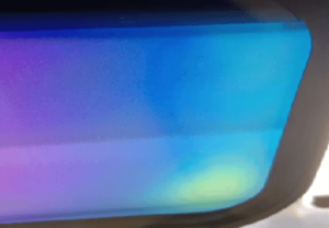
In the context of optical bonding for displays, some manufacturers interpret Mura as light leakage. Since this defect may appear as yellow spots or yellowish lines along the edges on a white screen, many manufacturers also refer to Mura as “yellowing.”
Mura Evaluation (Identification Method)
The simplest way to identify Mura is to switch the display to black, white, or low gray-level images in a dark room. By visually inspecting the edges around the active area (AA), one may observe irregular colors such as white, yellow, or other uneven patterns.
Observing the display from different angles will reveal various types of Mura phenomena, including stripes, patches, and clustered patterns, with no consistent color or shape. If pressure is intentionally applied to the display area, the existing Mura will intensify, and even after removing the external force, the Mura will not disappear immediately.
From the working principle of liquid crystal displays, Mura is essentially unavoidable whenever stress is applied to the liquid crystal cell—it can only vary in severity.
Based on the principle of camera lens filters, Fujifilm developed ND (Neutral Density) filters. These filters come in eight levels: 1%, 2%, 3%, 4%, 5%, 6%, 8%, and 10%. In the industry, Mura is typically classified and evaluated according to these levels.
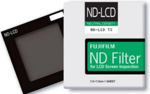
Neutral Density (ND) Filters
In ND filters, a 1% transmittance filter (ND100 or higher) is more “stringent” (i.e., has stronger light reduction capability) than an 8% transmittance filter (typically ND8 or ND12).
The lower the transmittance percentage of an ND filter, the less light it allows through, meaning it blocks more light and is therefore considered more “intense” or “stronger.”
Specific Comparison:
- 1% transmittance (approximately ND100–ND1000 or higher):
Belongs to strong ND filters, reducing light by more than 6–10 stops. Suitable for daytime long-exposure photography, such as capturing flowing water with a silky effect. - 8% transmittance (typically ND8–ND12):
Belongs to weak ND filters, reducing light by about 3 stops. Suitable for shooting in cloudy conditions or at dusk, with relatively mild light reduction.
In summary: The lower the transmittance percentage, the higher the ND value, and the stronger the light reduction capability.
Causes of Mura
Mura can originate from materials or processes in the front-end manufacturing of the display panel (PANEL), though the specific solutions for those are not discussed here. It can also result from materials and processes used during the back-end assembly stages.
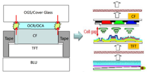
This article focuses only on Mura that occurs after optical bonding. Under the assumption that defects in the cover glass, panel, polarizer, backlight, and other materials have been ruled out, the discussion centers on Mura caused by deformation of the liquid crystal cell due to bonding-induced stress.
Typical examples include yellow spots and non-uniform display effects commonly observed after bonding.
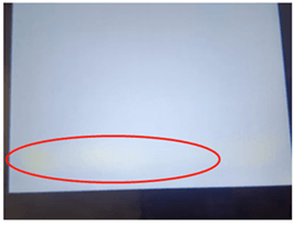
Failure Analysis of Defective Units: A detailed teardown analysis was conducted on defective units. Removing the housing showed no change, and removing the backlight also produced no change. However, after separating the CTP (capacitive touch panel) and TFT, the yellow spots disappeared. When the CTP was reattached and left to rest for several days, the yellow spots reappeared.
This confirms that the Mura defect in this case is related to the bonding materials or processes. In full-lamination processes—whether using OCA (optically clear adhesive) or liquid adhesive—Mura that appears after curing or after a period of rest is strongly related to adhesive selection and curing conditions.
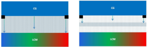
Impact of Optical Adhesive: First, considering the effect of optical adhesive: polymer-based adhesives tend to be relatively rigid. If the selected thickness is insufficient, their ability to absorb strain is poor. As a result, deformation stress affects the liquid crystal layer, transmitting mechanical distortion to the display. This leads to non-uniformity in the liquid crystal cell gap, causing uneven light transmittance and ultimately resulting in visible color non-uniformity—i.e., Mura.
Solutions for Mura
-
Increase adhesive thickness
A thicker adhesive layer can absorb more deformation stress. However, this will increase material costs, potentially even doubling them. Therefore, it is not recommended to use OCA with a thickness of 175 μm or thinner.
-
Reduce cover glass thickness
Thinning the cover glass can help reduce deformation. However, this may also decrease impact resistance and durability.
-
Use softer adhesive (lower elastic modulus)
Selecting a softer adhesive can help better absorb stress. However, if the adhesive is too soft, it may become difficult to handle during the bonding process.
-
Use laminated (multi-layer) structural adhesive
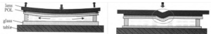
This type of adhesive combines the advantages of both thicker adhesive layers and improved stress absorption. It offers the best improvement effect. A schematic diagram of stress distribution after bonding can illustrate this advantage.
Single Layer OCA Sandwich OCA
-
Reduce bonding pressure appropriately
Minimize lamination pressure where possible, opt for backlight assembly after bonding, and ensure the bonding platform is as flat as possible. This helps reduce excessive compression and potential damage to the liquid crystal cell.
-
Improve shrinkage behavior of liquid adhesives
Select materials with lower curing shrinkage. In addition to changing adhesive materials, curing process parameters can also be optimized—for example, using low-intensity, longer-duration UV curing or gradual temperature ramp-up curing. These methods can help mitigate Mura to some extent.
If you have any questions, please contact our engineering.