Temperature Compensation for LCD Contrast & Voltage
LCD contrast and voltage change with the temperature. A LCD testing result is as below.

Fig. 1 Contrast vs Temperature |

Fig. 2 Voltage vs Temperature |
LCD voltage vs temperature – what you should know?
That is the reason the LCD looks lighter (blur) when the temperature drops, while the background appears (ghosting) when the temperature increases. There are some ways to improve the contrast with the temperature change, such as choosing the liquid crystal fluid changes less with temperature (Flat Fluid), or adding heater at the low temperature. Below, we will focus on using electronics to compensate the temperature change to increase the contrast.
For most applications this variation in contrast is tolerable over the “normal” temperature range of 0°C to +50°C. Most LCD modules are available with an extended temperature range option which allows the display to operate from -20°C to +70°C. The changes in LCD contrast temperature compensation are NOT usually tolerable over this wide a range of temperatures, which means a way of adjusting the contrast voltage as the ambient temperature changes should be provided.
How to optimize LCD temperature compensation
First of all, we want to optimize the contrast at room temperature, this is normally done during product development on the prototype unit. A LCD contrast potentiometer is connected between the appropriate power supply rails (Vdd and Vss for single supply, and Vee and Vdd for higher voltage LCD modules). The wiper of the pot is connected to Vo (LCD bias voltage input), see Fig. 3. The pot is adjusted to obtain the desired LCD appearance. Depending on the optimum contrast requirement, we can either leave the LCD contrast potentiometer in the design, or measure the voltage on the Vo pin and select a pair of resistors to produce this voltage in the production units.

Fig. 3 Power Supply
As the temperature decreases, the LCD fluid requires a higher operating voltage in order to maintain a given optical contrast. One way to provide for this is to give the user control of the contrast. This is a simple solution but normally it is not practical.
The microprocessor could measure the ambient temperature and supply the proper voltage to the LCD, but this is complicated and expensive.

Fig. 4 Temperature Compensated Voltage supplied by the Circuit
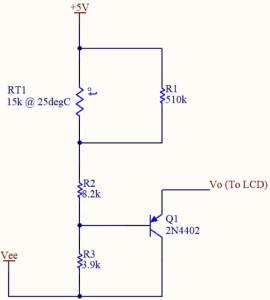
The most common solution to the LCD temperature compensation is to provide a circuit shown in Fig 5 to adjust the contrast voltage automatically.

Fig. 5 Simple Temperature Compensation Circuit
Fig. 5 uses a current buffer whose drive current is dependent on a thermistor (negative temperature coefficient). This thermistor, RT1 should be placed as close as possible to the LCD module to sense the ambient temperature experienced by the LCD.
The Vee level is dependent on the requirements of the LCD module. Extended character displays need -7.8V on VO at 25ºC or -2.8V with respect to ground (Vss). Note that Vee and VO are measured with respect to VDD supplies to the LCD. Typically, Vee is 25% greater than VO. During development, Vee is variable to optimize contrast.
Check Also: How does LCD work?


