The physical methods of connecting a core board to a baseboard depend on design requirements, cost, reliability, and the manufacturing process. Below are some common connection methods:
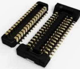
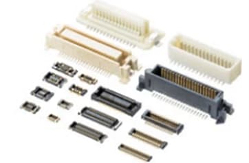
1. Socket Connectors:
- Utilizing board-to-board connectors, this is a very common method of connection. By using socket connectors, the core board can be inserted into a corresponding socket pre-installed on the baseboard. This type of connection is typically used in applications where the core board needs to be frequently replaced or upgraded, such as interfaces between computer motherboards and CPUs.
2. Direct Soldering:
- The pins or solder pads of the core board can be directly soldered onto the baseboard. This method provides a very stable and reliable connection, suitable for permanent installations where disassembly is not required, such as in certain embedded system applications.
- DIP (Dual In-line Package) Insertion: This refers to a specific type of direct soldering where components with DIP packaging are inserted into through-holes on the baseboard and then soldered.
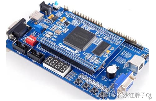
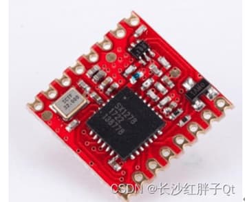
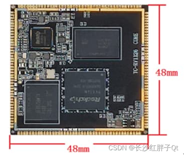
- Stamp Hole Technique:
-
- In this method, two boards are connected at their edges by a small strip of material featuring many tiny holes, facilitating easy breakage. After breaking, the edges of the boards resemble the perforated edges of a postage stamp, hence the name “stamp hole” for this type of paneling.
- As demand for modular circuit boards increases in printed circuit board manufacturing, the use of finer holes (also known as stamp holes) is becoming more common. For irregularly shaped PCBs, such as circular ones, stamp holes are used to facilitate panel connections, making them particularly useful in non-standard board designs.
- In terms of stability, the stamp hole design is considered optimal. While DIP pins and board-to-board connectors present challenges in wiring and soldering, and though board-to-board connectors can use surface-mounted imported interfaces, they are expensive and prone to poor contact after multiple insertions and removals. Stamp holes, on the other hand, offer low cost, ease of wiring, stability, and firm soldering with a low profile, making them the best choice for products requiring high shock resistance. However, stamp holes also present some difficulties, such as the challenge in testing to verify the integrity of the core board, and the risk that once soldered, it is difficult to remove without risking damage to both the core board and the baseboard.
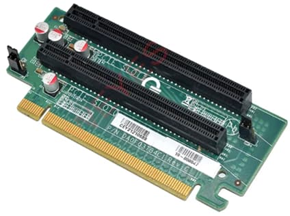
3. Slots and Edge Connectors, or Gold Fingers:
- The core board can be designed with edge connectors, which can be inserted into corresponding slots on the baseboard. This method is commonly used in PC components such as RAM sticks and graphics cards and is also suitable for some high-performance embedded systems. Edge connectors provide a reliable and quick method for assembling and disassembling components, facilitating upgrades and maintenance.
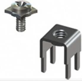
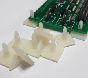
4. Screw Mounting or Standoffs:
- Screws are used to directly secure the core board to the baseboard. This method enhances physical stability, making it suitable for environments subject to vibration or other applications requiring additional mechanical fixation. Standoffs provide the necessary spacing and support to maintain board integrity and prevent electrical shorts, ensuring durable and reliable installations.
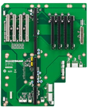
5. Backplane and Motherboard:
- In some large systems, multiple core boards or modules can be connected via a backplane, which in turn is connected to the main motherboard. This arrangement supports the high-density installation of core boards and is commonly found in servers and telecommunications equipment. The use of a backplane allows for centralized connectivity and power distribution, facilitating easier upgrades and maintenance while optimizing the performance and scalability of the system.
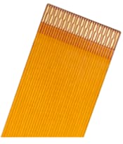
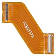
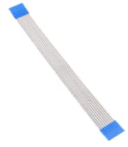
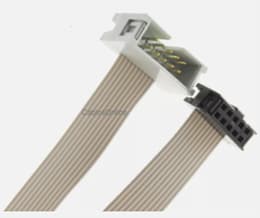
6. Flexible Flat Cables (FFC) or Ribbon Cables:
- Core boards and baseboards are connected using flexible cables, which provide a degree of physical positioning flexibility. This method is particularly suitable for devices with limited space or complex wiring requirements. Flexible flat cables and ribbon cables facilitate easier routing and connection in tight or intricate layouts, reducing the risk of damage during installation and maintenance while ensuring reliable signal transmission.
Each connection method has its specific applications, advantages, and disadvantages, and the choice of the appropriate method depends on the specific needs and budget of the project. If you have a particular project or design considerations, we can further discuss the most suitable connection solution.